Getting Started
If you’re using Surge 1.9, use the Manual for Surge 1.9.
Surge is accessible on Windows and macOS and works well with screen readers. See accessibility.
Surge XT is a virtual synthesizer originally released as “Surge” as open source by creator Claes Johanson in September 2018. Since then, it’s maintained by the Surge Synth Team, a group of volunteers.
This manual has main sections:
- Installing or building
- Interface and using Surge XT
- Accessibility
- Technical Reference, with specifications and details of the synthesis engine.
For tutorials, tips, and more content, see the Surge wiki.
To ask questions, report bugs or issues, or help develop Surge XT, visit the Surge Synth Team Discord server.
Most of the images and descriptions use the default Classic skin, and this manual uses macOS conventions (Title Case) for labels in the UI. The names of modifier keys are often shown together for PC/Mac respectively, i.e. Ctrl/Command or Alt/Option, although parts of this manual may just use PC keyboard labels.
Trademarks:
- Audio Units, AU is a trademark of Apple Computer, Inc
- VST is a trademark of Steinberg Media Technologies GmbH
Building From Source
To build Surge XT from source code, see our GitHub repository.
Installing Surge XT
Download the Surge XT installer from https://surge-synthesizer.github.io.
Windows
On the Windows platform, Surge XT installs optionally as:
- 32-bit VST3, with filename
Surge XT.vst3 - 64-bit VST3, with filename
Surge XT.vst3 - CLAP plug-in instrument, with filename
Surge XT.clap - Standalone executable, with filename
Surge XT.exe
System Requirements:
- Windows 7 or newer
- A reasonably fast CPU (Pentium 4/Athlon 64 or above)
- At least 4GB of RAM
- VST-compatible host application
To use the 64-bit version on Windows you also need:
- A CPU supporting the x64 (AMD64/EM64T) instruction set
- A 64-bit version of Windows
- An application to host 64-bit VST plug-ins
VST3 and CLAP versions of the plug-in install to default plug-in locations. If your host application does not find Surge XT, check that your application supports VST3 or CLAP, and make it scan for plugins.
Windows Portable Mode
- If Surge XT is installed alongside a
SurgeXTDatafolder, Surge XT will use that for factory data rather than the default%PROGRAMDATA%\Surge XT. - If Surge XT is installed alongside a
SurgeXTUserDatafolder, Surge XT will use that for user data rather than the default%DOCUMENTS%\Surge XT. - The About screen displays the folders Surge XT uses.
macOS
On macOS, Surge XT installs as a 64-bit Plug-in Instrument for the Audio Unit (AU), VST3, and CLAP plug-in interfaces, and as a standalone application.
System Requirements:
- Mac OS X 10.11 or newer
- A 64-bit x86 Intel or ARM Apple Silicon CPU
- At least 4GB of RAM
- 64-bit AU or VST-compatible host application
To install Surge XT, run the packaged installer. You have the option to install AU Surge XT.component, VST3,
and CLAP, along with factory patches and wavetables. The packaged installer installs Surge XT for all users
of your system.
Linux
On Linux, Surge XT is available as a 64-bit VST3 and CLAP as a deb and RPM package. It is also offered as a standalone application.
The system requirements can be hard to determine, as there are many Linux distributions, and other factors.
The installation package on the Surge XT website is a Debian package.
The distribution package is built on Ubuntu 18.04.
A list of required packages is listed in the source and in the deb file.
Note: You can use alternative gestures Alt/Option + Drag or the scroll wheel, which can conflict with the desktop environment. To solve that issue, disable the global gesture in the desktop environment.
Installing Alongside Older Versions
Surge and Surge XT are different plug-ins. This means that you can install Surge XT alongside Surge 1.9 or earlier. Keep Surge 1.9 installed to open projects that use older versions of Surge.
Standalone Version Options
If you are running Surge XT as a standalone executable, options at the top-left:
- configure MIDI and audio inputs and outputs
- save and open state files for the synth
- reset Surge XT to the default state
The BPM setting is to the left of the virtual keyboard at the bottom of the window. This sets the tempo for the Tempo Sync option in the context menus of time-related parameters.
Locations
Note: You can change these locations in the Surge XT main menu. See Data Folders.
Warning: If you reinstall Surge XT, you will lose any changes you made to the content of the factory folder, including custom patches and skins. The Surge XT installer never changes files the user area, so save your files there.
Windows
The patch library and wavetables are at C:\ProgramData\Surge XT.
The user patches are at C:\Users\your username\Documents\Surge XT.
macOS
The patch library and wavetables are at /Library/Application Support/Surge XT.
The user patches are at ~/Documents/Surge XT.
Linux
The patch library and wavetables are at /usr/share/surge-xt with a standard install.
The user patches are at ~/Documents/Surge XT. Surge XT creates this directory when you store a patch
or change the user default settings for the first time.
Playing Your First Note
Surge XT is best used with a DAW, or a physical device like a keyboard. To get started, you can open the virtual keyboard from the main menu > Workflow > Virtual Keyboard, or Alt/Option + K. See Workflow.
User Interface Basics
Surge XT displays four main sections: header, scene controls, modulation and routing, and effects.
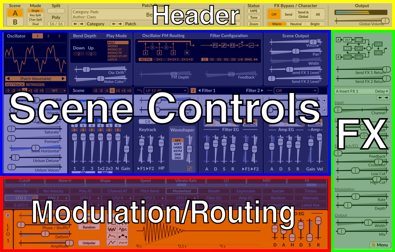
The four sections of Surge XT.
Scenes
Every patch in Surge XT contains two scenes (A & B) and an effects section. A scene is similar to a traditional synthesizer patch that stores all the information used to synthesize a voice. In a single patch, you can play a single scene, layer two scenes, or split the key range between two scenes. See Scene Select and Scene Mode.
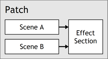
Audio Outputs
When loaded into a DAW, each instance of Surge XT has 3 audio outputs:
- Stereo Out
- Scene A Out
- Scene B Out
If your host allows, you can route and process those outputs separately.
Sliders and Controls
Surge XT parameters display as number fields, value fields, buttons, button groups, or sliders.
If you select anywhere in the slider control, it enters drag mode.
Slider movement:
- Left-drag moves the slider
- Shift + Left-drag moves the slider with fine control
- Ctrl/Command + Left-drag moves the slider in steps
- Scroll Wheel moves the slider 10% of its range
- Shift + Scroll Wheel moves the slider in small steps
Other slider actions:
- If you have Alt/Option pressed when you release a left-drag, the slider snaps back to its initial position
- Double Left-click resets the parameter to its default value
- Right-click displays the context menu
- Hover displays its value
Undo and Redo
To undo or redo your latest changes, select the curved arrow buttons to the left of the Save button below the Patch Browser. You can also press Ctrl/Command + Z to undo, and Ctrl/Command + Y to redo.
Parameter Context Menu
To display a parameter context menu, right-click.
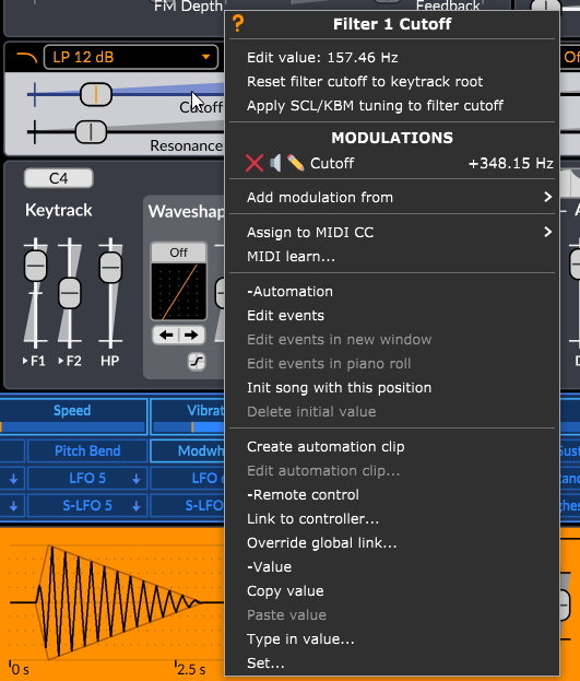
Name and Contextual Help
For help with a parameter, select the ? option, or hover the parameter and press F1.
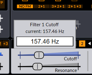
Edit Value
Select Edit Value then enter a value. There is no need to enter the unit of the entered value. Press Enter to commit the change. To exit without committing the change, press Esc or focus elsewhere.
For a discrete parameter, like Unison Voices or a button row, select a value from its context menu.
Extend Range
You can extend the range of some parameters, like Pitch. Select Extend Range from its context menu.
Tempo Sync
You can synchronize some parameters to the host tempo. Toggle Tempo Sync. With Tempo Sync enabled, a slider displays “TS”.
Note: Skins can display TS differently.
Enabled
You can enable or disable some parameters. Toggle Enabled in its context menu. A disabled slider displays dimmed or has no handle.
Modulations
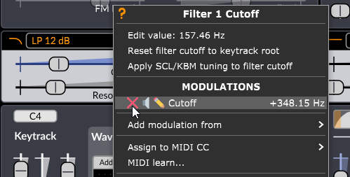
Surge XT can use a modulation source to adjust a parameter value. If a modulation is active, the slider track highlights, and its Modulations section displays in its context menu. Each row is a modulation. See Routing. For a modulation row:
- To clear a modulation routing, select the red X icon.
- To toggle bypassing a modulation routing, select the speaker icon.
- To edit the modulation amount, select the pencil icon and type a value. See Edit Value.
Add Modulation From
To select a new modulation source, select Add Modulation From, then select a modulation source and enter a modulation value.
Assign To MIDI CC
To assign the parameter a MIDI controller:
- Select Assign to MIDI CC from the parameter context menu.
- Select a MIDI controller code. You can select codes 0 to 127, but some codes are reserved for other uses.
- Optionally, to change the listened MIDI channel, select Assign to MIDI CC > MIDI Channel, and select a new channel or Omni.
You can select only one assigned or learned MIDI controller for a parameter.
MIDI Learn
To assign a MIDI controller to a parameter, select MIDI Learn from the parameter context menu, then move a controller on a connected MIDI device.
To exit MIDI learn, select Abort MIDI Learn from the parameter context menu.
You can select only one assigned or learned MIDI controller for a parameter.
Clear Learned MIDI
The assigned or learned MIDI controller displays next to Clear Learned MIDI in the parameter context menu.
To clear the assigned or learned MIDI controller, select Clear Learned MIDI.
Host-Provided Menu Options
If you use the CLAP or VST3 version of Surge XT, and depending on your host, options from your host may display at the end of the context menu. These options might help with automation, MIDI, or parameter values.
Header

In the header, you can select and manage patches, select scene modes, configure MPE, configure tuning, select zoom, bypass effects, and control and monitor output.
Scene Select and Scene Mode
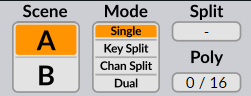
Select Scene buttons A or B to select a scene. The selected scene displays below.
To copy or paste a scene, right-click on Scene buttons A or B to display the context menu, then select Copy or Paste.
To select a Scene Mode, select:
- Single to play only the selected scene A or B.
- Key Split to play Scene A for notes below the Split key, and Scene B for notes including and above the Split key.
- Channel Split to play Scene A for channels below and including the Split MIDI channel, and Scene B for channels above the Split MIDI channel.
- Dual to play both scenes A and B.
If you disable MPE and select Scene Mode Key Split or Dual, channel 1 and channels 4 to 15 play the selected Scene Mode. Channel 2 plays only Scene A and channel 3 plays only Scene B.
Polyphony Limit
If you try to play more voices than the polyphony limit allows, Surge XT will stop a playing voice to make room for the new one. To change how Surge stops voices at the polyphony limit, see Note Priority and Play Mode options.
To change the polyphony limit, drag the Poly control up or down. Poly displays a count of playing voices.
Patch Browser
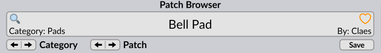
A modified or unsaved patch displays with an asterisk in the patch name area.
Note: To deactivate the Confirm Patch Loading dialog that protects you from losing unsaved changes, select Don’t ask me again when the dialog displays. You can also toggle this from the main menu > Workflow > Confirm patch loading if unsaved changes exist.
Navigation
To cycle through patches, select the Patch arrow buttons.
To cycle through patch categories, select the Category arrow buttons.
To select a random patch, middle-click the Patch or Category arrow buttons.
To select a patch in the current category, right-click the Patch Browser area where the patch name displays, then select a patch.
To list all patches, select the Patch Browser area where the patch name displays. In the pop-up, patch categories display in columns:
- Factory Patches were created by authors of Surge 1.6. Select a category, then a patch.
- Third Party Patches were contributed by users and the Surge Synth Team. Select a creator name, then a category, then a patch.
- User Patches are your own patches. You can choose how to categorize these patches. Favorites are patches where you selected the Favorite heart icon.
The patch browser also supports MIDI program changes.
Loading More Patches
To directly load a .fxp patch file, drop it onto the Surge XT window.
To download additional content, select Download Additional Content from the main menu at the bottom-right of the window, or from the window context menu.
Managing Patches
To set the current patch as default when you open a new instance of Surge XT, select Set Current Patch As Default from the patch context menu.
To rename a user patch, select Rename from the patch context menu.
To delete a user patch, select Delete from the patch context menu.
Searching Patches
To search patches by name, select the magnifier glass icon to the left of the patch name area, then start entering text.
Note: Surge XT might first take a moment to update its patch database.
You can also search metadata:
- To search by author, enter
AUTHOR=orAUTH=, then part of the author name. - To search by category, enter
CATEGORY=orCAT=, then part of the category name.
By default, the list closes when you select a patch. To leave the list open, select main menu > Workflow > Retain Patch Search Results After Loading. To close the list with this enabled, press Ctrl/Command while selecting a patch, or press Esc.
The Save Dialog
A modified or unsaved patch displays with an asterisk in the patch name area.
To save a patch, select Save, or press Ctrl/Command + S.
Hint: To bypass the Save dialog when Confirm Patch Loading is enabled, hold Shift when confirming with OK.
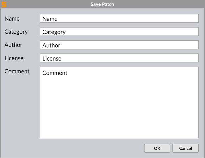
- Enter a Name for your new patch
- Choose a Category, or start typing to list matching categories, or create a new category. Note: you can use subfolder categories, but these might be skipped by category navigation arrows.
- Enter Author as you wish to be identified.
- Enter a License for how your patch may be used. For example,
Licensed under the maximally permissive CC0 license. - Enter Comments. Comments display when you hover over the patch name.
Favoriting Patches
To favorite a patch, select the heart icon in the patch name area. To load a favorite patch, right-click the heart icon to display the Favorites list and select a patch.
Status Area

Select MPE to toggle MPE mode. Right-click to open a context menu of MPE settings.
Select Tune to toggle custom tuning. If there is no custom tuning, this opens the Tuning context menu.
Select Zoom to open the context menu and change the size of the Surge XT window, or set its default size.
You can also access MPE settings, Tuning, and Zoom from the main menu.
FX Bypass, Character, Global Volume
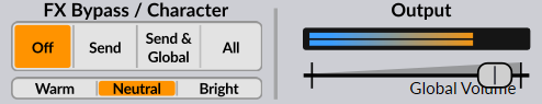
Select an effects type to deactivate:
- Off activates all effects.
- Send deactivates send effects.
- Send + Global deactivates send and global effects.
- All deactivates all effects.
Character shapes the timbre of oscillators. Select Warm, Neutral, or Bright.
Global Volume is the final gain stage.
To change clipping of global output, right-click Global Volume then select a Global Hard Clip option from the context menu:
- At +18 dBFS (default),
- At 0 dBFS
- Disabled
Warning: Change Global Hard Clip with care. Loud sounds increase the risk of damaging equipment or hearing. You should also limit sounds in your DAW or downstream equipment. Take special care with feedback, effects, and resonance features.
Level Meter
The level meter displays the current output level. Levels above 0 dBFS display red.
To open the oscilloscope, press Alt/Option + O, or right-click on the level meter and select Oscilloscope. The oscilloscope displays a waveform or a spectrum.
To display CPU usage in the level meter, right-click on the level meter and select Show CPU Usage.
Scene Controls
Sound is generated then shaped.
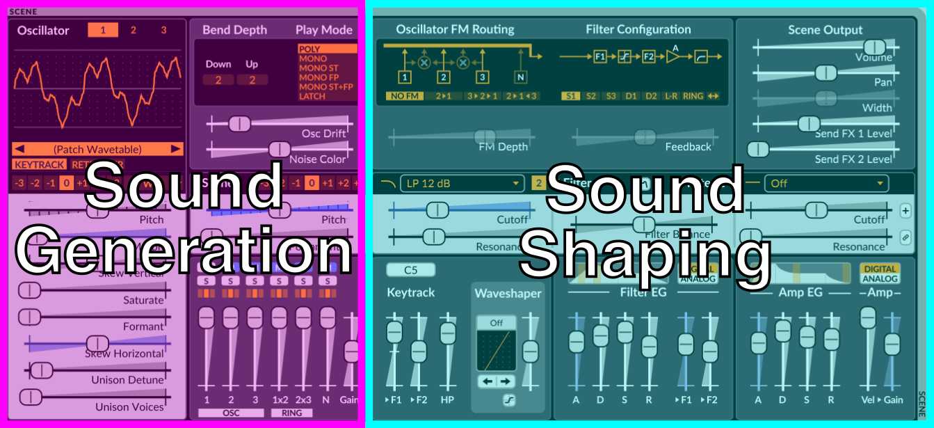
Sound Generation
When you play a note, oscillators generate waveforms and send them to the mixer.
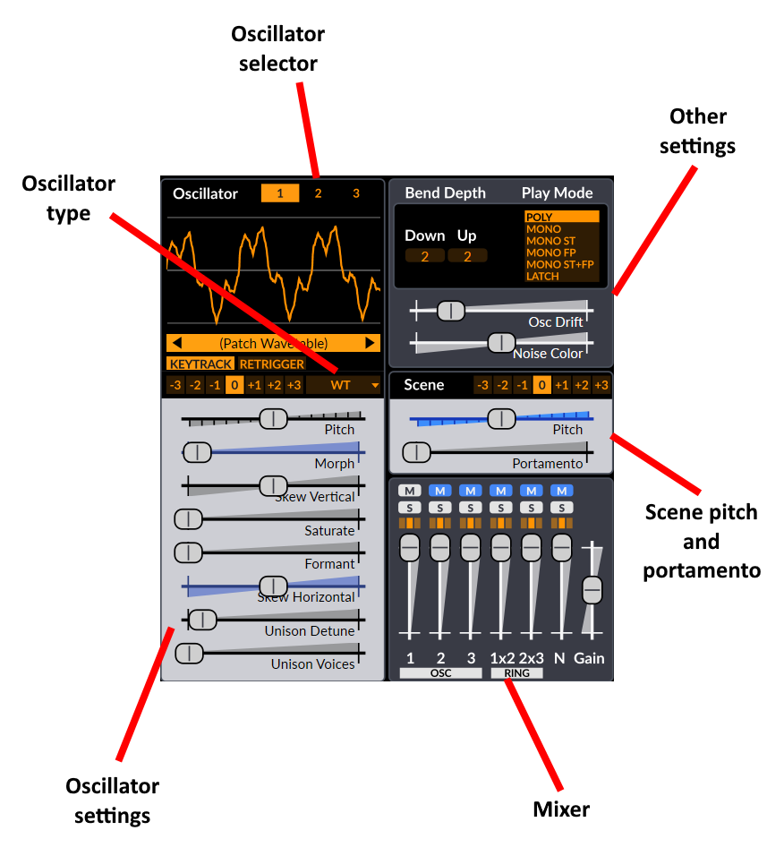
Oscillators
To display an oscillator for editing, select Oscillator buttons 1, 2, or 3. If the oscillator is muted in the mixer, the waveform displays dimmed.
To copy an oscillator, right-click 1, 2, or 3, then select Copy or Copy with modulation from the context menu.
To change oscillator algorithm, select the drop-down list at the bottom-right of the oscillator area:
- Classic
- Modern
- Wavetable
- Window
- Sine (default)
- FM2
- FM3
- String
- Twist
- Alias
- S&H Noise
- Audio Input.
To select a wavetable with Wavetable or Window oscillators, select the wavetable name or its arrow buttons, or you can right-click to select within the current wavetable category.
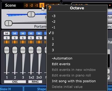
Pitch
Pitch & Octave control the pitch for the oscillator.
To extend the range of the Pitch control, select Extend Range from the context menu.
To select a pitch offset in Hz, instead of a semitone (note degree) offset, select Absolute from the context menu.
Keytrack
To toggle key tracking for the oscillator, select or unselect Keytrack. When unselected, the oscillator plays at a fixed pitch that is the same for all notes.
To toggle key tracking for all oscillators, right-click Keytrack then select Enable Keytrack For All Oscillators or Disable keytrack for all oscillators.
Retrigger
To toggle retriggering for the oscillator, select or unselect Retrigger. When active, each voice starts with the oscillator and all its unison voices at the same phase position.
To toggle retriggering for all oscillators, right-click Retrigger then select Enable Retrigger For All Oscillators or Disable Retrigger For All Oscillators.
Hint: When you enable Retrigger, each note onset sounds more consistent or ‘snappy’. When you disable Retrigger, the onset can sound more varied and less ‘digital’.
Other Oscillator Controls
Other controls are specific to each oscillator type.
Mixer
Mixer Channels
The mixer controls six channels, and a Pre-filter Gain:
- Oscillator 1
- Oscillator 2
- Oscillator 3
- Ring Modulation of 1 × 2
- Ring Modulation of 2 × 3
- Noise Oscillator
Surge XT uses ‘digital ring modulation’, multiplying the raw output of two oscillators.
To choose a ring modulation mode, right-click a slider, and select Ring Modulation, Continuous XOR, or Scale-Invariant Linear Modulation types 1 to 9.
You can also apply ring modulation to the pair of filter outputs with Filter Configuration > Ring.
Channel Parameters
To change gain for a channel, move its slider.
To mute a channel, select M. Select again to unmute.
To mute a channel and unmute the other channels, hold Ctrl/Command and select M.
To solo a channel, select S. Select S again to unsolo. If any channel has solo enabled, then the mixer ignores all mutes.
To solo a channel and unsolo the other channels, hold Ctrl/Command and select S.
To select which filters a channel routes to, select from the group of three boxes:
- Left routes the channel output to filter 1.
- Center routes the channel output to filters 1 and 2.
- Right routes the channel output to filter 2.
See also: filter configuration.
Scene Pitch and Octave
To offset the pitch of the scene, move the Pitch slider. To offset the pitch of the scene by whole octaves, select a Scene Octave from -3 to +3.
Note: Scene pitch parameters add to keytrack values used by Filter 1 Keytrack, Filter 2 Keytrack, and to the Keytrack modulation source.
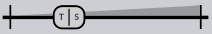
Portamento
To change the time for pitch to change from one note to the next, move the Portamento slider.
From the Portamento context menu:
- To sync portamento time with the tempo, select Tempo Sync.
- To make portamento change pitch at a constant rate, enable Constant rate. Portamento is then the time to move over one octave. When Constant rate is disabled, portamento time is the same for all notes.
- To quantize portamento to pitch degrees (semitones), enable Glissando.
- To retrigger envelope generators (FEG and AEG) as pitch crosses scale degrees, enable Retrigger at scale degrees.
- To change the portamento curve, select Curve options, then Logarithmic, Linear (default) or Exponential.
Oscillator Drift
To independently vary the pitch of all oscillators and their unison voices, enable Osc Drift.
To also randomize the pitch at the very start of the note, right-click and enable Randomize initial drift phase.
Noise color
To shape the timbre of the noise generator, move the Noise Color slider:
- Low frequencies to the left
- White noise in the middle
- High frequencies to the right.
Bend Depth
To control the pitch wheel range, from 0 to 24 semitones:
- left-click Bend Depth > Down or Bend Depth > Up, and then drag up or down.
- hover over Bend Depth > Down or Bend Depth > Up, and use the scroll wheel.
- right-click Bend Depth > Down or Bend Depth > Up, select Edit value from the context menu, and enter a value. You can also enter decimal numbers, fractions, and cents.
Play Mode
To select a play mode, select from the Play Mode list, or right-click and select from the context menu.
- Poly mode lets you to play many notes at the same time, up to the polyphony limit.
- Mono modes only play one note, which depends on note priority. By default, the latest note has priority.
- Latch mode is like Mono FP, but immediately starts playing note C5, and holds the latest note continuously without releasing.
Poly Play Mode
With Play Mode set to Poly:
- To use a new voice for a replayed note, select Stack Multiple. This is also known as ‘round robin’, and is the default.
- To reuse a voice that is already playing the same note as your new note, select Reuse Single.
Mono Play Modes
- Mono mode plays only the latest note.
- Mono (ST) or Mono (Single Trigger) mode does not retrigger the envelope generators when sliding between two overlapping notes.
- Mono (FP) or Mono (Fingered Portamento) mode applies portamento only between overlapping notes.
- Mono (ST+FP) or Mono (Single Trigger & Fingered Portamento) combines Mono (ST) and Mono (FP) modes.
To set note priority, right-click the Play Mode area and select one of:
- Last to play the latest note only. When released, play the latest remaining note. This is the default option.
- High to play the highest note only. When released, play the highest remaining note.
- Low to play the lowest note only. When released, play the lowest remaining note.
- Legacy to play the latest note. When released, play the highest remaining note.
To set envelope retrigger behavior, right-click the Play Mode area and select one of:
- Reset To Zero to reset envelopes to the beginning of the attack stage when you start a note. This is the default option.
- Continue From Current Level to make envelopes continue from the level of the previous note.
To set behavior when the sustain pedal is pressed in mono mode, right-click the Play Mode area, select Sustain pedal in mono mode, then select one of:
- Sustain pedal holds all notes (no note off retrigger) to stay on the priority note when you release that note. This is the default option.
- Sustain pedal allows note off retrigger to switch to the remaining priority note when you release the priority note.
Sound Shaping
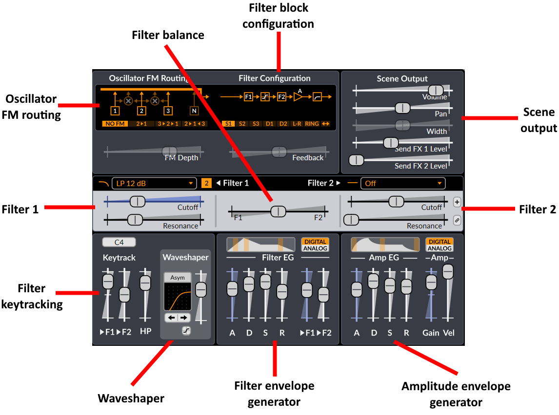
Filter Controls
To select how the filters, waveshaper, and gain stage connect together, select a Filter Configuration:
- Serial 1 routes the signal from the Mixer goes into Filter 1, then into the Waveshaper, then into Filter 2, then the Amplifier which contains the Amplifier Envelope Generator (AEG), before going through the Scene Highpass and to the final Scene Output section.
- Serial 2 is the same as with Serial 1, plus a feedback path from the output of the Amplifier back into Filter 1.
- Serial 3 is the same as with Serial 2, but Filter 2 is in the feedback loop, which is after the signal tap from the Amplifier instead of before.
- Dual 1 routes the signal from the Mixer to both Filter 1 and Filter 2 in parallel. The outputs from both filters are summed, then sent to the Waveshaper, then into the Amplifier, and finally in the Scene Highpass before the Scene Output section. Feedback is again tapped at the output of the Amplifier and goes back into both filters (it’s summed with the output from the Mixer).
- Dual 2 is the same as with Dual 1, except the Waveshaper is only applied to Filter 1 before its output is summed with the output from Filter 2.
- Stereo is the same as with Dual 1, except Filter 1 is always on the left channel and Filter 2 is always on the right channel.
- Ring is the same as with Dual 1, except the outputs from Filter 1 and Filter 2 are multiplied (ring modulated) together instead of being summed before the Waveshaper.
- Wide is the same as with Serial 2, except it’s doubled for a full stereo signal path.
Notes:
- Only Stereo and Wide output a stereo signal.
- If you set Filter Configuration to S1, S2, S3, or Wide, then any output from filter 1 then routes to filter 2, so Left or Center routes pass through both filters in turn.
- If you set Filter Configuration to Ring, then to hear sound, you need to route some sound to each filter.
- If you set Filter Configuration to Wide, then Left and Right routes are hard-panned to stereo positions.
Feedback
To set the amount (and polarity) of output fed back into the input of the filter block, move the Feedback slider. It has no effect for Serial 1, because that configurations has no feedback path.
Warning: Take special care with feedback, effects, and resonance features. Loud sounds increase the risk of damaging equipment or hearing. You should use the limiter on Global Volume, and in your DAW or downstream equipment.
Hint: Feedback is a creative technique that helps you change the character of filters, make filters interact together, create basic physical models, or make unstable sounds.
Filter Balance
To control how the two filters mix in the filter block configuration, move the Filter Balance slider.
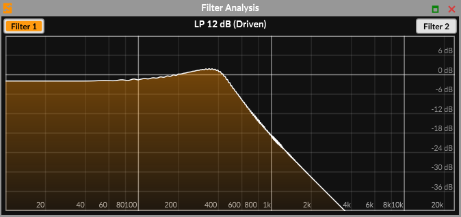
Filter Type and Filter Subtype
To select the filter type for Filter 1 or Filter 2, select the dropdown list, then select a Filter Type. You can also hover over the list and use the scroll wheel, or right-click and select a Filter Type in the context menu.
To select a filter subtype by name, right-click the subtype number and select a Filter Subtype from the context menu. See Filters. To cycle through filter subtypes, select the Subtype number next to the dropdown list, or hover over the subtype number and use the scroll wheel.
To enable or disable the filter without changing the filter type, right-click on the dropdown list and toggle Enabled.
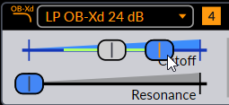
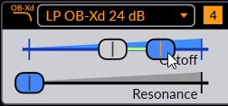
Filter Cutoff
To select the cutoff frequency of a filter, move its Cutoff* slider. As you move the slider or hover over it, a tooltip displays the frequency value in Hz and its approximate MIDI note name.
To set the Cutoff frequency to the Keytrack Root* frequency, right-click the slider and select Reset cutoff to keytrack root. Hint: this helps you to tune filters with Filter Keytrack.
Finally, the Apply SCL/KBM tuning to filter cutoff option can be accessed when the Apply tuning after modulation option is enabled in the Tuning menu. See the microtuning section for more information.
Hint: MIDI note names help when you use the filter for melodic and tuning purposes. To snap to the frequency of the nearest note, hold Ctrl/Command while you drag the slider.
Filter Resonance
To control the resonance of a filter, move its Resonance slider.
Filter Analysis
To open the Filter Analysis window, select on the small button above the filter balance control.
To view a filter, select Filter 1 or Filter 2 buttons.
To change the Cutoff and Resonance, drag the display horizontally to change Cutoff, and drag vertically to change Resonance.
Filter 2 Offset Mode
To link Filter 2 Cutoff frequency to that of Filter 1, select the Filter 2 Offset Mode button (a small + button to the right of the filter parameters)
When filter 2 offset mode is active, the Cutoff frequency slider of Filter 2 is an offset relative to the Cutoff frequency of Filter 1. When you change the Cutoff frequency of Filter 1, Filter 2 follows. This includes any modulations, FEG depth, and Keytrack.
To link the Filter 2 Resonance to that of Filter 1, select the Link Resonance button (a small chain link button).
When link resonance is active, the Resonance slider of Filter 2 is an offset relative to the Resonance of Filter 1. When you change the Resonance of Filter 1, Filter 2 follows.
Filter Keytrack
To control how much the pitch of a note affects the cutoff frequency of a filter, move the Keytrack > F1/F2 sliders. At 100% keytrack, the filter frequency follows the pitch harmonically.
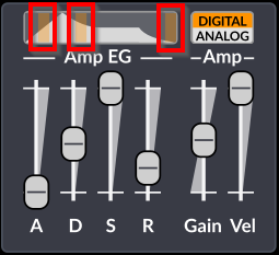
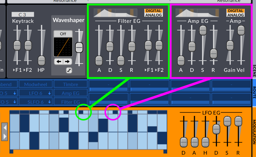
Envelope Generators
Envelopes shape your sound over time.
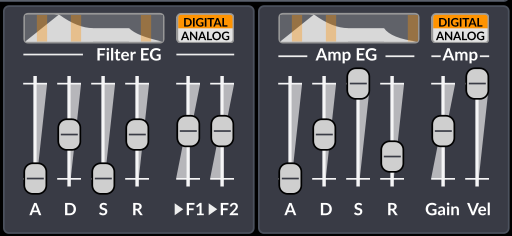
To modulate Filter 1 or Filter 2 with the filter envelope, move FEG Mod Amount sliders >F1 and >F2.
To scale the amplitude envelope, move the VCA Gain (Amp /> Gain) slider.
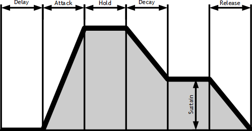
Filter and amplitude envelopes in Surge XT use ADSR stages: Attack, Decay, Sustain, and Release.
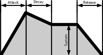
After passing through attack and decay stages, the envelope stays in the sustain stage until you release the note.
To tempo sync any envelope stage, right-click then select Tempo Sync, or Tempo Sync For All … EG Parameters.
Release parameters have an additional option in the context menu, Freeze Release at Sustain Level, which retains the output level at which the envelope was upon releasing the key for the whole duration of the release stage. This allows better shaping of the release stage with LFO, MSEG or Formula modulators, since the resultant amplitude will not be affected by the decaying nature of the release stage.
To change how the envelope curves to the next stage, select Analog or Digital from the … Envelope EG Mode list.
- Analog emulates the curves of analog envelope generators.
- To change the curves of Digital envelopes, select or drag to move the highlight on the envelope graph, or right-click and select an option from the context menu. Depending on the stage, options Convex, Linear, Quadratic, and Concave are available.
Waveshaper
A waveshaper transforms each sample through a shaping function (‘x to y’ graph). For example, a Saturator pushes sample values away from 0 and towards the outer limits of the wave.
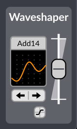
Note: The waveshaper applies at different places in different filter configurations. For example, in Filter Configuration S2 it applies between Filter 1 and Filter 2, but in Filter Configuration D1, it applies after both filters.
To select a shaping function, right-click the graph or select the label, then select a Waveshaper Type from the context menu. You can also select the arrow buttons, or hover and use the scroll wheel.
To apply gain before the waveshaper, move the Waveshaper Drive slider.
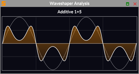
To view the effect that the waveshaper has on a sine wave, select the small Waveshaper Analysis graph icon.
Other Sound Shaping Parameters
Keytrack
To change the root key used as the center for keytracking, drag the Keytrack Root Key control up or down, hover and use the scroll wheel, or right-click and select Edit Value.
At the root key, the keytrack modulation source has a value of zero. Higher notes have positive values, and lower notes have negative values. When you modulate another parameter with Keytrack, the modulation amount you set represents the modulation applied for a note one octave above the Keytrack Root Key. Keytrack Root Key does not change oscillator pitch.
To control how much the pitch of a note affects the cutoff frequency of a filter, move the Keytrack > F1/F2 sliders. At 100% keytrack, the filter frequency follows the pitch harmonically.
Scene Highpass Filter
To change the cutoff frequency of the scene high-pass filter, move the HP (Highpass) slider.
To disable Highpass, right-click the slider and unselect Enabled from the context menu.
To change the filter slope of the high-pass filter, right-click the slider and select a Slope:
- 12 dB/Oct
- 24 dB/Oct
- 36 dB/Oct
- 48 dB/Oct
Oscillator FM Routing
To select how FM (frequency modulation) routes through oscillators, select one of:
- No FM
- 2 > 1
- 3 >2 > 1
- 2 > 1 < 3
To set the depth of oscillator FM, move the FM depth slider.
Velocity Sensitivity
Surge XT has a simple way to make your patch ‘velocity sensitive’.
To select a VCA Gain (Amp > Gain) for the lowest possible key velocity, move the Amp Vel. slider. Amp Vel. has no effect at the maximum position of 0 dB. If you play a key at maximum velocity, Amp Vel. has no effect.
VCA Gain (Amp > Gain) controls the gain element inside the filter block.
Scene Output
To set the gain of the selected scene, move the Volume slider. The output stage is after the filter block, so scene volume has no effect on the timbre of the voice before the effects stage.
To select clipping for the selected scene, right-click the Volume slider, and in the context menu, select one of:
- Scene … Hard Clip Disabled
- Scene … 0 dBFS
- Scene … +18 dBFS (default)
To mute the current scene, right-click the Volume slider, and select Mute scene A/B in the context menu. Hint: If you feed audio of scene A into scene B with the Audio Input oscillator, you’ll likely want to mute scene A. This also mutes the signal to Scene A insert effects.
To set stereo panning for the scene, move the Pan slider. Around -80% is hard left, and around +80% is hard right. To set stereo spread for the scene, move the Width slider. Width is active only for filter configurations Stereo and Wide.
To send the scene output to Send FX slots 1..4, move the Send FX … Level sliders. To display sends 3 and 4, select one of those FX units in the Effect Unit Selector.
Modulation/Routing
The modulation section is different from the sound generation and shaping sections as no audio data is passed through it. Instead it allows you to control the parameters in the other sections from various sources.
Routing
Modulation routing in Surge XT is a bit different compared to most synthesizers, but it’s actually very intuitive and extremely powerful, thanks to the routing bar.

How To Apply Modulation
Here’s how it works:
- Select the modulation source you want to use.
- Engage routing mode with a second click on the source. It will become bright green, and sliders that can be modulated with that source will display a blue modulation depth slider on top of their normal sliders.
- Drag the desired modulation slider (blue slider) to the position you want the parameter to be at when fully modulated (at the top peak of a Sine LFO, or after the attack stage of an envelope for example). The modulation’s full range will then be shown with the corresponding range bar indicator on the slider.
- Disengage routing mode by clicking again on the modulation source.
Alternatively, routing mode can also be engaged or disengaged by pressing the middle mouse buttons anywhere over the interface, or by pressing TAB on the keyboard if this option is enabled (see Workflow section in the menu).
You can also directly access the numerical modulation amount dialog (explained here) by dragging the desired modulation source over a modulatable parameter.
Note that modulation range is always relative to the base value represented by the gray slider, meaning that moving its position will then shift the whole modulation range up or down. This also means that if a modulation slider’s value is smaller than the base value, the modulation polarity will be inverted.
Also, when applying modulation to certain time-based parameters (such as Portamento, envelope attack, etc.) that are set to 0.00 seconds, in some cases, the modulation won’t trigger properly due to the way it works internally. To fix this, simply increase the parameter in question by a very small amount, just so it doesn’t have a value of 0.
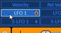
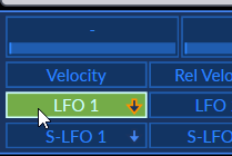
Modulating a Modulator
When clicking on one of the LFO buttons in the routing bar, both the LFO source selection and the LFO editor will be selected. However, the two actions can be done separatly, as you can choose which button is selected as the modulation routing source, and at the same time edit parameters from a different LFO than the source.
To do that, select the source normally, and then click on the mini-button on another LFO (the small orange arrow):
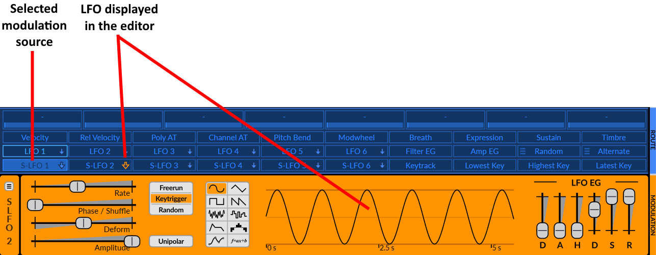
Alternatively, you can also left-click on a modulation source while holding Ctrl/Command to display it in the LFO editor as well.
This effectively lets you modulate the parameters of one LFO with any other mod source(s). However, as an example, note that logistically, an S-LFO can modulate parameters of an LFO, but an LFO cannot modulate parameters of an S-LFO (see Voice vs Scene Modulators).
Remember that you can also see which LFO is currently being displayed in the editor by looking at what’s written vertically to the left of the editor.
Modulated Sliders
Once a slider is routed to a modulation source, the shade of blue on its tray indicates whether the parameter is modulated and by which source.
-
Parameter is not modulated (gray)
-
Parameter is modulated (gray-blue)
-
Parameter is modulated by the currently selected modulation source (bright-blue)
Moreover, if you hover your mouse pointer over any modulated slider, the source(s) it’s being modulated from will be highlighted in the routing bar. This makes it easier to see what modulation source(s) are linked to a parameter.
Modulation Source Selectors
Once routed to any parameter, the modulation source selectors change their appearance depending if they are selected, and if they are routed in the current patch or not. (scene dependent)

-
Unused modulation source
-
Used modulation source
-
Unused selected modulation source
-
Used selected modulation source
Some modulation source selectors in the routing bar have a hamburger menu. This serves as an indicator that different types of that modulation source are available. You can access them directly by clicking on that hamburger menu, by right-clicking and going into the Switch to… submenu, or simply by scrolling with the mouse wheel over the modulation source selector in question.
Clearing Modulation
After right-clicking on a modulated slider, you will see an option to easily clear the modulation and un-link it from its source.
Alternatively, you can also reset its modulation slider (blue slider) to 0 by double-clicking on it when routing mode is engaged, or entering 0 in the type-in editor (see Edit Value).
Furthermore, by right-clicking on any modulation source, there will be options to clear a particular linked parameter, but also all of them at once.
Modulation List
Surge XT has a detailed modulation list that can be displayed by clicking on the vertical rectangular button at the left of the routing bar:
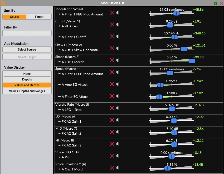
This panel will display the modulation routings and their amounts from both scenes in the current patch. Different display options are available to the left of its interface:
Sort by - Allows you to choose whether the list of modulations is grouped according to the source they are coming from or to the target they are routed to.
Filter By… - This option allows you to only display certain modulation routings by hiding those that aren’t included in the desired source or target in this list.
Add Modulation - These two menus allow you to directly add a new modulation routing directly from the modulation list panel. Simply select a modulation source and a modulation target to link a modulator to a parameter.
Value Display - Allows you to choose between 4 different display options regarding the modulation values displayed in the sliders section, ranging from None to Values, Depths and Ranges.
Finally, in the sliders section, you can both adjust the different modulation amounts, but also directly mute or remove a modulation routing entirely.
Modulators
Surge XT has four main types of modulation sources :
- LFOs
- Internal modulators
- Voice and note properties
- Macros
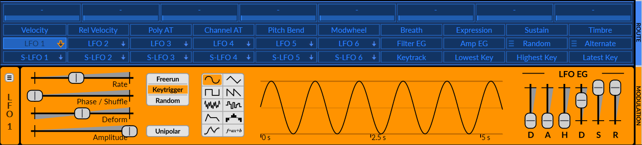
All of these modulation sources are located in the routing bar (see Routing) :
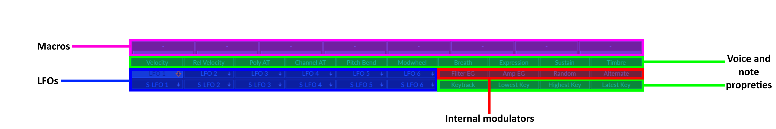
The four types of modulation sources, separated in categories.
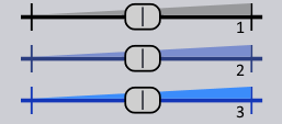
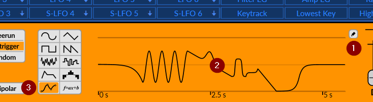
Voice vs Scene Modulators
Some modulation sources operate at the voice level, while others operate at the scene level. Although they might seem similar, there is an important factor that distinguishes them.
On one hand, a voice modulator has separate modulation paths for each voice, meaning it can control voice-level parameters (like filter cutoff) but cannot control scene-level parameters (like FX levels or scene pitch).
On the other hand, a scene modulator has one identical modulation path for the whole scene, so it can control both scene level parameters and voice level parameters.

On top, three voice LFOs. On the bottom, three Scene LFOs, “S-” meaning Scene.
To demonstrate this distinction, let’s say an sine wave LFO is modulating the cutoff of a filter. Now, if 3 notes are being hit with a small delay between each of them, the phase of the LFO will be delayed between the notes accordingly.
You will indeed clearly hear the cutoff of the filter moving independently for each note, which gives the impression that there are three LFOs and three filters (which there actually is!). The same principle applies for envelopes.
However, unlike the first demonstration, this time, if an S-LFO is modulating a certain parameter, hitting more notes will not “add” an LFO for each voice, which gives the impression that there is a single LFO modulating the cutoff frequency of the filter instead of many.
See Modulation Routing Details in the Technical Reference section for more information.
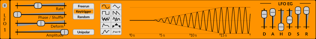
LFOs
Unlike some other synthesizers, Surge XT does not have dedicated LFO, Envelope, Step sequencer or MSEG modulation sources. Instead, those are integrated within every LFO. This effectively enables the flexibility of having up to 12 LFOs, envelopes, step sequencers or MSEGs, and everything in between simply by changing their shape.
Surge XT’s LFOs are very flexible and come with a built in DAHDSR-envelope which can either work as a dedicated envelope generator or shape the amplitude of other modulation types over time.
Surge XT has a total of 12 LFOs:
- 6 Voice LFO sources (labeled LFO 1-6 for instance)
- 6 Scene LFO sources (labeled S-LFO 1-6 for instance)
See Voice vs. Scene for an explanation about the difference LFOs and S-LFOs.
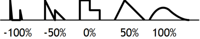
Shapes
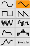
LFO shapes (from left to right, top to bottom):
| Sine | Sine wave LFO | Vertical bend |
| Triangle | Triangle wave LFO | Vertical bend |
| Square | Pulse wave LFO | Pulse width |
| Sawtooth | Sawtooth wave LFO | Vertical bend |
| Noise | Smooth noise LFO | Correlation |
| S&H | Sample & Hold (stepped noise) LFO | Correlation |
| Envelope | Envelope generator - sets the LFO to a constant output of 1, which can then be shaped by the LFO EG (see LFO Envelope Generator) | Envelope shape |
| Step Seq | 16 step step-sequencer (see Step Sequencer). | Smoothness/Spikyness |
| MSEG | Fully editable MSEG (Multi-Segment Envelope Generator) with a large number of curve types and various editing options (see Envelope Generator) | Depends on segment type and configuration |
| Formula | Script (Lua) enabled formula modulator | Depends on the coded modulation |
On the left, the different shapes and their explanation. On the right, the way that the Deform parameter affects the waveform.
Depending on the selected shape for a particular LFO, its name in the routing bar will change. When using the first 6 waveforms, it will be called LFO. However, when using the envelope shape, ENV will be displayed, SEQ will be displayed when the step-sequencer is used, and for the MSEG, MSEG will be displayed. Scene LFOs have their equivalent labels as well:
Parameters
Rate – Controls the modulation rate. When the type is set to Step Seq, one step equals the whole cycle. This slider can be tempo-synced and disabled from its context menu. Deactivating the rate effectively freezes the LFO to a certain constant value set by the Phase/Shuffle parameter. This can be useful for manually scrubbing in a waveform cycle of an LFO for instance, and can also be used in the same way in the sequencer. This feature can also be used to make the modulation source act as a randomizer in tandem with the “Random” trigger mode. A simpler Random (see Internal Modulators) modulation source can however also be used for that purpose. Furthermore, modulation can even be applied to the Phase/Shuffle parameter with another modulation source which opens up a lot of possibilities, such as effectively using the frozen LFO as a mod mapper.
Note: In the LFO editor, when right-clicking parameters that can be tempo-synced, there will also be an option to Tempo sync all the LFO parameters at once.
Phase/Shuffle - Controls the starting phase of the modulation waveform. As with any parameter, it can be modulated. However, in this case, its modulated value will not change after the modulation is triggered (for instance, it’s not possible to shift an LFO’s phase while a note is pressed). Only starting phase is taken into account. This control can also be extended, allowing for bipolar shuffle, useful for adding swing in the step sequencer.
Amplitude – Controls the amplitude of the modulation. This is the parameter you should use if you want to control the depth of an LFO with a controller (like controlling vibrato depth with the modulation wheel, for instance). This control can also be extended form its context menu, which allows you to reach a negative amplitude range (-100 to 100% instead of 0 to 100%).
Deform – Deform the modulation shape in various ways. The effect varies depending on the selected shape. Different deform types are available for the Sine, Triangle, Sawtooth, S&H, Envelope and Step Seq shapes, and can be accessed by right-clicking on the Deform slider.
Trigger mode – Chooses how the LFO is triggered when a new note is played:
- Freerun – The LFO’s starting phase is synchronized with the host’s song position to make it continuously running in the background. The modulation will be trigged at its starting phase when playback position is either at the beginning position and the song starts playing, or when playback position goes back at the beginning of a loop for instance. Freerun behaves the same on voice LFOs or scene LFOs.
- Keytrigger – The LFO’s starting phase is triggered when a new note is pressed. If the synth is set to “Poly”, each new voice gets its own LFO triggered with it when using a voice LFO. However, when using an scene LFO, the first voice sets the LFO’s position, then the other ones will follow it.
- Random – The LFO’s starting phase is set to a random point in its cycle. If the synth is set to “Poly”, each new voice gets its own LFO triggered with it when using an voice LFO. However, when using an scene LFO, the first voice sets the LFO’s position, then the other ones will follow it.
Unipolar - If active, the modulation will be in the [0 .. 1] range (unipolar). If not, it will be in the [-1 .. 1] range (bipolar).
The modulation range on a parameter is represented by a green bar when routing mode is engaged (see Routing).
Modulation on a control from a bipolar source
Modulation on a control from a unipolar source
LFO Envelope Generator
The Envelope Generators are of the 6-stage DAHDSR type that are multiplied with the waveform generator, no matter what the selected LFO shape is. This means that if the LFO shape is set to Envelope, the output will simply be 100%, and can then be shaped by the LFO EG.
Also, note that when using the Envelope shape, the envelope will always trigger on key trigger, no matter what the trigger mode is set to.
The LFO envelope generator can be completely disabled by right-clicking on one of its controls and unchecking the Enabled option.
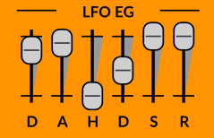
6-stage DAHDSR envelope
Step Sequencer
The Step Seq shape houses a step sequencing editor where the LFO display would be. It allows you to draw the output waveform with up to 16 steps.
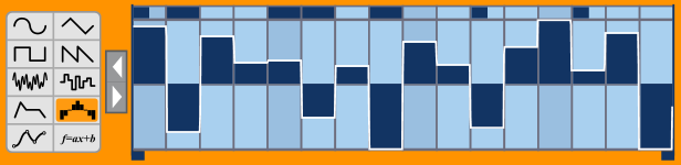
Step Sequencer editor
The two blue markers define loop-points in which the sequence will repeat once it gets into the loop. The left mouse button is used for drawing while the right one can be used to clear the values to zero.
To quickly reset a step to 0, either double-click on a step, or hold down Ctrl/Command and click or drag with the mouse over the desired step(s).
Right-clicking and dragging over steps allows you to draw a straight line over the desired steps, thus creating a perfectly linear staircase pattern.
Holding down Shift while drawing will quantize the values to the scale degrees (1/12th in case of standard tuning, or possibly other for custom tuning) spanning the range of one octave. Furthermore, holding down Shift + Alt/Option makes two times more values available, hence useful when modulating pitch by two octaves instead.
For more information on microtonal pitch modulation using the step sequencer, visit our Tuning Guide.
The step sequencers inside voice LFOs have an extra lane at the top of the step editor allowing to re-trigger the two regular voice envelopes (The Amplifier and Filter Envelope Generators) when the small rectangle is filled at that particular step.

Step Seq of LFO 1 containing the re-trigger pane
However, shift-clicking or right-clicking those rectangles allows the specified step in the sequencer to only trigger one of the two envelopes. When the step is half-filled on the left, only the filter envelope will be triggered. When filled on the right, only the amplifier envelope will be triggered.
The Deform parameter gives the Step Seq waveform a lot of flexibility. A value of 0% will output the steps just as they look on the editor. Negative values will give an increasingly spiky waveform while positive values will make the output smoother.
| Negative deform | 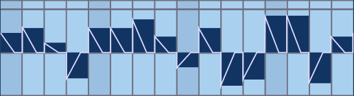 |
| Positive deform | 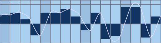 |
Effect of the deform parameter on the step Seq waveform
Multi-Segment Envelope Generator
Surge XT’s Multi-Segment Envelope Generator (MSEG) is powerful and fully editable with a large number of curve types and various editing options. It can be used to create more complicated LFO waveforms or envelopes compared to the previously mentioned modulation shapes. With the combination of various settings in the editing window and the usual parameters from the LFO editor, you can practically create any modulation shape you could think of.
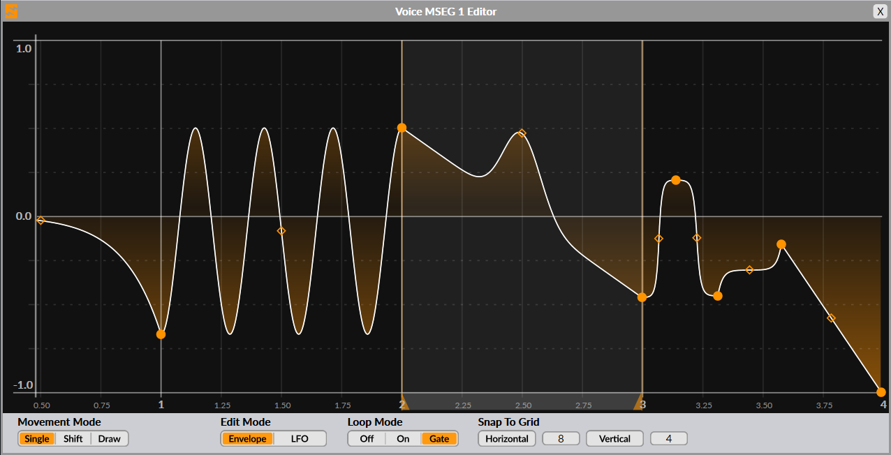
To open this MSEG editing window, you can either click on the little pencil button next to the wave display (1), click on the wave display itself (2), or double-click on the MSEG icon in the modulation type selector (3):
Default MSEG state
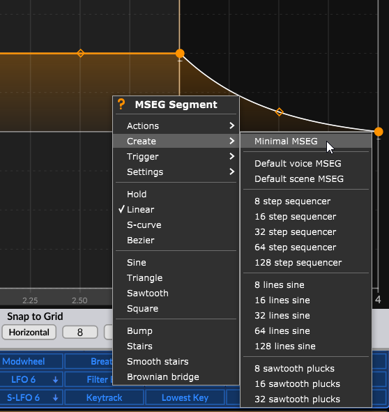
Once opened, you will see a shape working as an envelope if you’re using a voice LFO, or a triangle wave working as an LFO if you’re using a scene LFO. In any case, you can either build upon these shapes if they suit your needs, or you can reset them to a simple straight line by right-clicking anywhere in the edit window, then choosing Create -> Minimal MSEG. More information on those menu entries can be found below.
Zooming and panning
In the MSEG editor, you can pan the view left or right by either left-clicking or middle-clicking, then drag on the background left or right.
You can also zoom in and out by either scrolling with the mouse wheel or left-clicking then dragging your mouse up or down. Alternatively, you can again middle-click and drag if you prefer.
Moving nodes
To move a node, simply left-click and drag it. To do the same with multiple nodes at the same time, you can Shift + left-click and drag, which makes a selection.
Adding and removing nodes
In Surge XT’s MSEG, a segment is comprised of its starting node (point) and the segment itself. A “segment’s end node” is actually the next segment’s starting node. To add a new node, simply double-click where you want it to be added. To remove a node and its following segment, simply double-click on the node you want to remove. Note that you can only remove nodes if there are more than two nodes remaining in the shape.
Control points
In addition, you will also often find a control point in the middle of a segment. This one can be dragged vertically (and also sometimes horizontally) to alter the segment’s curvature or other properties depending on the line type. To reset a control point to its default position, simply double-click on it.
MSEG editing and behavior options
At the bottom of the editor are a couple of options to configure editing modes and general behavior of the MSEG:
-
Movement Mode - Sets the behavior when moving nodes.
- Single - When dragging a node horizontally, moves a single node without affecting the others.
- Shift - When dragging a node horizontally, shifts around the nodes following the node being moved, keeping the length of the segment belonging to that node constant.
- Draw - Locks horizontal dragging of nodes, allowing you to draw over existing nodes to set their value in a simple sweeping motion.
-
Edit Mode - Configures the MSEG editor to work in Envelope or LFO mode.
- Envelope - Displays draggable loop points and region (effectively representing the Sustain stage in an envelope).
- LFO - Hides the draggable loop points and region, links the value of the start and end nodes to complete the waveform cycle, always keep loop mode enabled (even if set to off).
-
Loop Mode
- Off - Don’t loop when in Envelope mode, turn off draggable loop points.
- On - Loop forever in the loop region (between the loop points). Subsequent segments, if any, will never be reached.
- Gate - Loop until the note is released, then immediately transition to the segments following the loop region.
-
Snap To Grid
- Horizontal - Enables horizontal snapping to the grid. The number field to the right corresponds to the horizontal grid resolution. You can also temporarily enable horizontal snapping by holding down the Ctrl/Command key while dragging.
- Vertical - Enables vertical snapping to the grid. The number field to the right corresponds to the vertical grid resolution. You can also temporarily enable vertical snapping by holding down the Alt/Option key while dragging.
Segment options
Each segment has options in a context menu which can be accessed with a right-click in the area of that segment. Some of them are only applied to the right-clicked segment, while others are applied to the whole shape:
-
Actions
- Split - Splits the segment into two by adding a new node in its center
- Delete - Remove the segment and its starting node
- Double duration - Doubles the total duration of the whole shape
- Half duration - Halves the total duration of the whole shape
- Flip vertically - Flips the whole shape vertically
- Flip horizontally - Flips the whole shape horizontally
- Quantize notes to snap division - Quantizes the nodes in the whole shape to the nearest horizontal grid position. Available in Envelope edit mode only.
- Quantize notes to whole units - Quantizes the nodes in the whole shape horizontally to the nearest whole time units. Available in Envelope edit mode only.
- Distribute nodes evenly - Distributes the existing nodes from the whole shape evenly in the horizontal axis between the first and last node.
-
Create
- Minimal MSEG - Loads a straight line going from 1 to 0 in value, a great starting point to build upon.
- Default voice MSEG - Loads the default voice MSEG preset (envelope shape).
- Default scene MSEG - Loads the default scene MSEG preset (triangle wave LFO shape).
- 8 to 128 step sequencer - Replaces the existing shape by an 8 to 128-step sequencer shape.
- 8 to 128 sawtooth plucks - Replaces the existing shape by an 8 to 128 sawtooth plucks shape.
- 8 to 128 lines sine - Replaces the existing shape by a sine wave made out of 8 to 128 segments.
-
Trigger
- Filter EG - Triggers the hardwired filter envelope generator at that point.
- Amp EG - Triggers the hardwired amplifier envelope generator at that point.
- Nothing - Disables the triggering of both the filter and amplifier envelope generators at that point.
- All - Enables the triggering of both the filter and amplifier envelope generators at that point.
-
Settings
- Link start and end nodes - Links the value of the start and end nodes (useful for seamless looping for example).
- Deform applied to segment - Sets if the selected segment is affected by the Deform parameter found in the LFO editor or not (see deform parameter).
- Invert deform value - Inverts the deform polarity applied to the selected segment.
-
Segment types - List of line types from which a segment can be. The control point, if present, will have a different effect depending on the type used.
- Hold - Holds the value of the previous node up to the segment’s end node. No control point available.
- Linear - Single line. The control point controls the curvature of the segment.
- Bezier - Single line. The control point can freely bend the segment.
- S-curve - Curved line. The control point determines how abrupt the S-shape is and its direction.
- Bump - Single line. The control point can be moved up or down to create a “bump” in the segment.
- Sine, sawtooth, triangle, square - Sine, sawtooth, triangle or square waves. The control point determines how many wave cycles there are between the segment’s beginning and end node.
- Stairs, smooth stairs - Stair or smooth stairs line types. The control point determines how many steps there are between the segment’s beginning and end node.
- Brownian bridge - Random between the beginning and end node every time it’s being triggered. Moving the control point down adjusts the number of steps while quantizing them up to 24 equidistant steps (useful for random scales, for instance). Moving the control point up also adjusts the number of steps, but this time without any quantization. The horizontal value of the control point adjusts correlation.
Formula
The Formula modulator shape is a fully-fledged and Lua-enabled scriptable modulation source. Although this shape may not be as straight forward to use and to understand as the others listed above, in its complexity hides true modulation power, which technically-geared users will truly appreciate.
Surge XT comes with a series of tutorials for the formula modulator available in the patch browser, each of them explaining different aspects and ideas you can re-create in the formula editor:
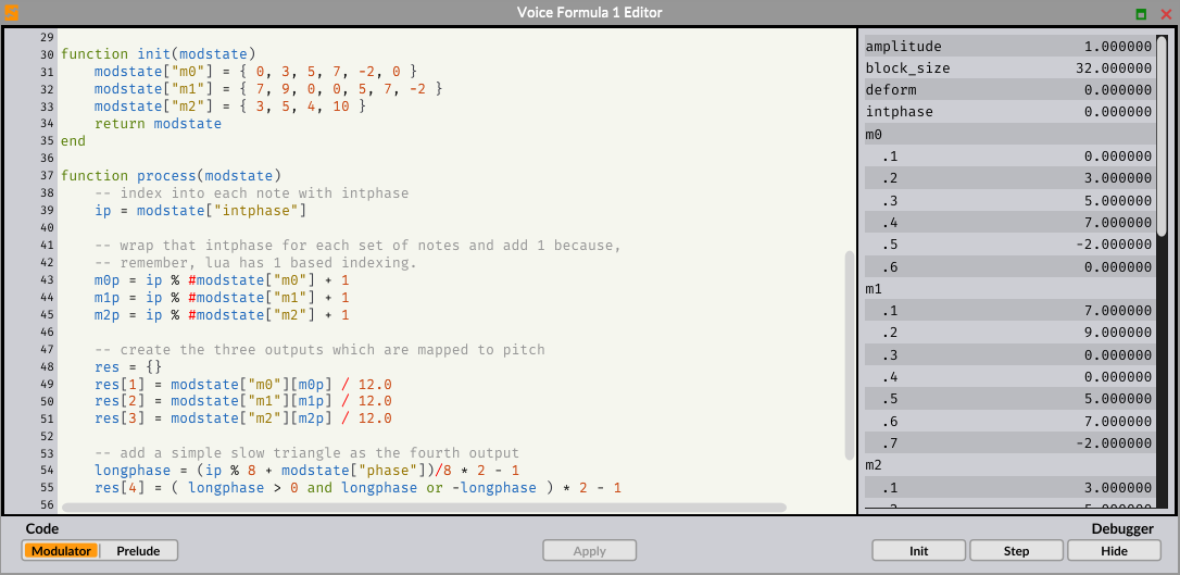
These tutorials are definitely worth consulting, but here are some basic principles that may help you get started with the formula modulator.
Every formula modulator instance must contain at least a process function. This is where the modulator output will be set or calculated.
Different variables can be accessed (and some modified), allowing you to create the desired modulation behavior:
| amplitude | Value of the modulator’s Amplitude parameter | Ranges from 0 to 1 |
| attack | Value of the modulator’s Attack parameter | Ranges from 0 to 1 |
| block_size | Audio buffer size used by Surge XT | |
| cc_breath | Breath controller signal | Ranges from 0 to 1 |
| cc_expr | Expression controller signal | Ranges from 0 to 1 |
| cc_mw | Modulation wheel value | Ranges from 0 to 1 |
| cc_sus | Sustain pedal value | Toggles between 0 or 1 |
| chan_at | Monophonic aftertouch if MPE is disabled | Ranges from 0 to 1 |
| clamp_output | Can be set to false to disable the output range limit | |
| cycle | Alias for intphase | |
| decay | Value of the modulator’s Decay parameter | Ranges from 0 to 1 |
| deform | Value of the modulator’s Deform parameter | Ranges from 0 to 1 |
| delay | Value of the modulator’s Delay parameter | Ranges from 0 to 1 |
| highest_key | Keytrack value corresponding to the highest note played | +1/-1 per octave centered at middle C |
| hold | Value of the modulator’s Hold parameter | Ranges from 0 to 1 |
| intphase | Integer value set to the number of cycles that have been executed | |
| is_voice | Is set to true when the modulator is a voice modulator | |
| latest_key | Keytrack value corresponding to the latest note played | +1/-1 per octave centered at middle C |
| lowest_key | Keytrack value corresponding to the lowest note played | +1/-1 per octave centered at middle C |
| macros | See tutorial Macros And Voice Parameters (#6) | |
| output | Output value of the Formula modulator itself (see also clamp_output) | Outputs between -1 and 1 by default |
| pb | Current value of pitch bend | Ranges from -1 to 1 |
| pb_range_dn | Pitch bend down range | Set as Bend Depth in the UI |
| pb_range_up | Pitch bend up range | Set as Bend Depth in the UI |
| phase | Continuous value representing the real-time phase position of the modulator output | Cycles from 0 to 1 |
| poly_limit | Polyphony limit | |
| rate | Value of the modulator’s Rate parameter | Ranges from -7 to 9 |
| release | Value of the modulator’s Release parameter | Ranges from 0 to 1 |
| released | Is set to true when the modulator is in the release state | |
| retrigger_AEG | Can be set to true to trigger the Amplitude EG | |
| retrigger_FEG | Can be set to true to trigger the Filter EG | |
| samplerate | Host sample rate | |
| songpos | Host song position | |
| startphase | Value of the modulator’s Phase slider | Ranges from 0 to 1 |
| subscriptions | See tutorial Macros And Voice Parameters (#6) | |
| sustain | Value of the modulator’s Sustain parameter | Ranges from 0 to 1 |
| tempo | Host tempo | |
| use_envelope | Can be set to false to disable the LFO Envelope Generator shaping the modulator output |
In addition to the list above, Formula voice modulators also have access to these variables:
| channel | MIDI/MPE channel that triggered the modulator | |
| key | Key that triggered the modulator | MIDI note number |
| mpe_bend | Current MPE Pitch bend value | Ranges from -1 to 1 |
| mpe_bendrange | MPE Pitch bend range | Set in the MPE menu |
| mpe_pressure | MPE Pressure | Ranges from 0 to 1 |
| mpe_timbre | MPE Timbre | Ranges from 0 to 1 |
| poly_at | Per note polyphonic aftertouch | Ranges from 0 to 1 |
| rel_velocity | Per note release velocity value | Ranges from 0 to 127 |
| velocity | Per note velocity value | Ranges from 0 to 127 |
You can access or modify those values by using the following syntax:
state.*variable-name*
To see a list of values corresponding to those variables, you can open the integrated Debugger by clicking on the Show button at the right of the interface. This debugger also allows you to initialize the modulator by clicking on Init, and to step through the code using the Step button.
Since Formula is an indexed modulator, you can have up to 8 different outputs on a single formula modulator instance. This can be done by assigning the output to an array of values instead of a single value. An example of this can be seen in the tutorial Both Time And Space (#10).
After entering code or modifying existing code, press the Apply button for changes to take effect. You will see the output display update with the new shape.
Finally, you can switch to the Prelude view of the code by clicking on the corresponding button. The Surge prelude is loaded in each surge session and provides a set of built in utilities we’ve found handy in writing modulators.
LFO Presets
To the left of the Rate parameter, a small menu icon can be found. Clicking on it will reveal options to save the selected LFO state, open previously saved states, and finally rescan presets to update the list. Presets will be categorized by modulation shape.
Raw Waveform and EG Only Outputs
Each LFO is comprised of three distinct modulation outputs: the full LFO, the raw waveform, and the envelope generator only.
While the full LFO output (default) will send the resulting LFO shape modulated with the integrated envelope generator, switching to Raw Waveform from the modulation source context-menu will bypass the envelope, and Envelope Generator Only will set aside the LFO shape itself and only produce an output from the envelope generator. Those three outputs are treated as three separate modulation sources.
Right below, there is an option to apply the Amplitude parameter to still affect the Raw Waveform and Envelope Generator Only outputs of that modulator.
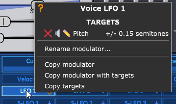
Copy/Paste Options
Finally, after setting up an LFO, its settings with or without its targets can be copied and pasted to another LFO. To do this, simply right-click on the source LFO in the routing bar and use the desired Copy option, depending on what you want to replicate on the new modulation source. Then, use the Paste option to paste it.
Renaming
LFOs and S-LFOs can be renamed to be more representative of their role and to help the user keep track of what each modulation source is doing in a patch. To do this, simply right-click on the LFO or SLFO in question, select Rename Modulator… and enter the desired name.
For more information on LFO algorithms, see LFOs in the Technical Reference section.
Internal Modulators
Filter EG
The Filter Envelope Generator modulation source, which is labeled “Filter EG”, is simply a modulation source corresponding to the output of the Filter EG, which as its name suggests is already hardwired to the filter modules. Other parameters can also be modulated by the Filter EG by various amounts, simply by routing them to this source.
Amp EG
The Amp EG modulation source, which is labeled “Amp EG”, is simply a modulation source corresponding to the output of the Amp EG, which as its name suggests is already hardwired to the output amp module. Other parameters can also be modulated by the Amp EG by various amounts, simply by routing them to this source.
Random
This modulation source operates at voice level. It will generate a single random value inside the modulation range for each voice every time a voice is played.
By default, this modulation source is bipolar and its value distribution is uniform. However, you can switch to a unipolar and normal versions of it by right-clicking on it and selecting Switch to…, and then choosing the desired type from the list. All of those can be used at the same time, so they can be considered independent modulation sources.
Note that multiple parameters routed to that modulation source will all receive the same value (in percentage). To send different randomized values to different parameters, multiple LFOs can be configured in a way to do this and with greater control. See the explanation of the Rate parameter.
Alternate
This modulation operates at the voice level. It will generate alternating values between the two modulation range’s extremums.
By default, this modulation source is bipolar. However, you can switch to a unipolar version of it by right-clicking on it and selecting Switch to -> Alternate Unipolar. The two can also be used at the same time, so they can be considered two independent modulation sources.
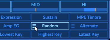
Voice and Note Properties
Like other synthesizers, Surge XT receives MIDI data to determine what note(s) to play. However, it can also use MIDI CC data to modulate any routable parameter.
There are 14 of those voice and note properties in the routing bar:
| Velocity | Per note velocity amount | Voice modulator | Unipolar |
| Release Velocity | Per note release velocity amount | Voice modulator | Unipolar |
| Polyphonic Aftertouch (labeled Poly AT) | Per note polyphonic aftertouch | Voice modulator | Unipolar |
| Channel Aftertouch (labeled Channel AT) | Monophonic aftertouch if MPE is disabled | Scene modulator, Voice modulator in MPE mode | Unipolar |
| Pitch Bend | Pitch bend wheel value | Scene modulator | Bipolar |
| Modwheel | Modulation wheel value | Scene modulator | Unipolar |
| Breath | Breath controller signal | Scene modulator | Unipolar |
| Expression | Often used in pedals and for crescendos or decrescendos | Scene modulator | Unipolar |
| Sustain | Sustain signal, often from a pedal | Scene modulator | Unipolar |
| Timbre | Primarily used for MPE controllers | Voice modulator | Bipolar |
| Keytrack | Per note keytrack value | Voice modulator | Bipolar |
| Lowest Key | Keytrack value corresponding to the lowest note played | Scene modulator | Bipolar |
| Highest Key | Keytrack value corresponding to the highest note played | Scene modulator | Bipolar |
| Latest Key | Keytrack value corresponding to the latest note played | Scene modulator | Bipolar |
Note that only scene-level modulation sources can be routed to FX sends and parameters. For instance, you can use Latest Key instead of Keytrack to modulate FX parameters, as Keytrack is a voice-level modulation. See Voice vs. Scene modulators for more details.
Macros
There are 8 macros, and by default, they are blank.
What separates these assignable controllers from the rest is that with a right-click, they can be assigned to a MIDI controller or any MIDI CC signal, and their value can be edited on-screen with the blue digital slider below their names.
By default, the macros are assigned to midi CC 41-48, which is often mapped by default to knobs or slider banks for a lot of midi controllers.
See MIDI CC Information in the Technical Reference section for more information.
The right-click context menu also allows you to rename the controller. There is also the typical routing and clearing options, (see Routing) and you can choose if their modulation is bipolar (both positive and negative with 0 in the middle) or unipolar (just positive).
Macros can also be dragged and dropped over other macros to make them switch place. To do so, simply left-click + drag over the desired macro slot location.
Finally, note that macros are considered global modulators, meaning they are shared between and act on both scenes A and B. This is useful in case you would want to quickly control certain parameters from both scenes in a single place.
Effects
The FX Section controls the 16 effect units of the effect block stored in every patch.
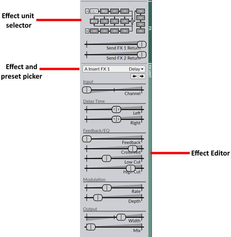
Effect Unit Selector
The effect unit selector can be found towards the top of the FX section. It also represents the signal path of the effects block. Here it is in more detail:
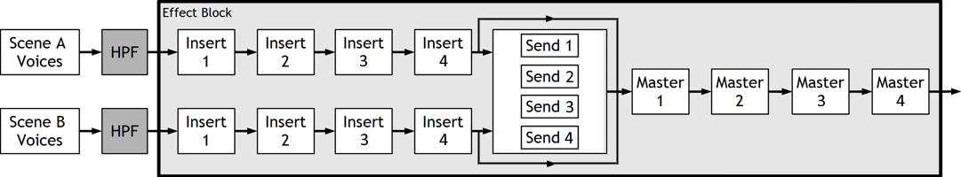
The effect block
A left-click on a particular unit in the effect unit selector brings that unit in the editor. A double-click on a unit disables/enables it. This state is stored within patches, unlike the global FX bypass setting. A right-click on a unit displays the effect and preset picker specifically for that unit, allowing you to directly add or swap an effect on that unit. An Alt/Option + Click clears the desired FX unit.
Moreover, you can drag-and-drop units over other units to make them switch places. Holding down Ctrl/Command and dragging allows you to duplicate (copy) units on other units instead, and holding Shift allows to simply replace (overwrite) the target unit with the source one.
Finally, you can right-click on either the A or B icons in the diagram to bring up output hard clipping options, which are the same as explained earlier in the Scene Output and Global Volume sections.
Effect and Preset Picker
Effects can be added or removed from the Effect and preset picker (just below the FX return sliders). You can also cycle through effects and presets using the same arrow buttons as those found in the global Patch Browser.
You can also save your own effect presets which will be stored globally with the synth. Finally, at the bottom of this menu, there are Copy and Paste options, which allows you to copy an effect and its parameters and paste it on another unit. You can also use drag-and-drop gestures to accomplish this (see Effect Unit Selector).
Effect Editor
This is where every effect parameter can be edited. Like with the oscillator editor, the parameter of each slider will change depending on the loaded effect.
Here’s a list of the available effects:
- EQ
- Exciter
- Graphic EQ
- Resonator
- Bonsai
- CHOW
- Distortion
- Neuron
- Tape
- Waveshaper
- Combulator
- Frequency Shifter
- Nimbus
- Ring Modulator
- Treemonster
- Vocoder
- Chorus
- Ensemble
- Flanger
- Phaser
- Rotary Speaker
- Delay
- Reverb 1
- Reverb 2
- Spring Reverb
- Airwindows
- Conditioner
- Audio Input
- Mid-Side Tool
See Effects in the Technical Reference section for more information about each effect.
Note: remember that FX parameters are scene controls. This means that only scene-level modulation sources can modulate them.
Microtuning
Surge XT has become known as a good synth for microtuning. It features full keyboard microtuning support using two different modes, Scala SCL/KBM and MTS-ESP, as well as from its internal Tuning Editor. Here we will focus on explaining the options in Surge XT’s Tune menu, one by one. If you want to learn more about the different tuning workflows, and the pros and cons of each of them, please visit our Tuning Guide
While using either of the modes, the Tune and Filter Cutoff menus will dynamically change to reveal the relevant tuning-related options. Also note, with any tuning mode active, left-clicking the Tune label in the status area simply turns the tuning mode on or off. To access the menu from this state, right-click instead
Default
By default, Surge XT tunes incoming MIDI notes the same way (nearly) every other software instrument does: To 12 equal divisions of an octave (12edo for short), with middle C tuned to 261.626Hz as a reference note (which makes A=440).
From this default state, opening the tuning menu shows you this:
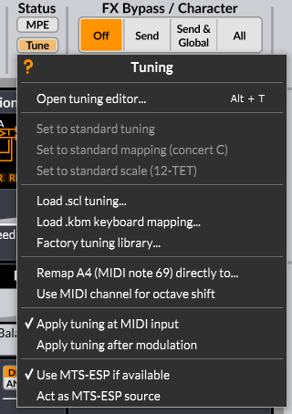
The tuning menu in default mode
The options near the top pertain to the Tuning Editor and SCL/KBM mode of retuning, the ones at the bottom to MTS-ESP. Let’s go through the menu options one by one, and also briefly describe the advantages of each tuning method.
Tuning Editor
The first option on the previously shown menu opens Surge XT’s built in tuning editor, which can change the intonation of the current Surge XT instance (and other instances and instruments too, via MTS-ESP, more on that later). Its function is described in more detail in our Tuning Guide
Scala SCL/KBM Mode
Scala SCL/KBM uses small plain text files to give tuning information to an instrument. For more general information about this method, refer to our Tuning Guide
Once in SCL/KBM mode, the tuning menu looks like this:
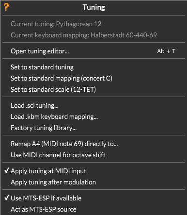
The tuning menu with an SCL/KBM pair loaded
-
Current tuning - Once an SCL file has been loaded, the description line of the tuning will appear here.
-
Current keyboard mapping - Once a KBM has been loaded, the file name of the keyboard mapping will appear here.
-
Open tuning editor… - As mentioned above, opens the Tuning Editor
The following three options are grayed out in the default menu, but become available once SCL/KBM files are loaded. Their purpose is returning the instrument to standard intonation settings:
-
Set to standard tuning - Resets the currently loaded SCL tuning table to 12 tone equal temperament, keeping the currently loaded KBM.
-
Set to standard mapping (Concert C) - Resets the currently loaded KBM such that the 1/1 of the loaded SCL is mapped to middle C.60 at 261.626 Hz, keeping the current SCL.
-
Set to standard scale (12-TET) - Resets both of the above.
The next three options are for loading SCL/KBM files. These can also be imported via drag-and-drop anywhere on the Surge XT interface:
-
Load .scl tuning - Loads .scl files.
-
Load .kbm keyboard mapping - Loads .kbm files.
-
Factory tuning library - Clicking on this option will open the system file browser at the location of the included Surge XT factory SCL/KBM content.
Then come some auxiliary options:
-
Remap A4 (MIDI note 69) directly to… - Instead of using a .kbm file, this option lets you directly type in the frequency (in Hz) of MIDI note 69, A above middle C.
-
Use MIDI channel for octave shift - Enables users of generalized array keyboard controllers (such as the Lumatone) to map large tuning gamuts and equal-temperaments contiguously across all 16 MIDI Channels.
Then follow two options which determine how Surge XT’s internal modulators will relate to the tuning information:
-
Apply tuning at MIDI input - Selected by default. When checked, the tuning is only applied to MIDI input, but pitch modulation is in 12-tone equal temperament amounts. So for example, a pitch bend of 2 always means 200 cents, whether or not your chosen tuning has a 200 cent interval.
-
Apply tuning after modulation - When checked, pitch modulation is instead tuned to the loaded scale. For instance, this means that a pitch bend of 2 always lands on the same frequency as the note two steps up, even in tunings with unequal step sizes.
Since choosing between one of the two options explained above fundamentally changes how a patch would play in tuned mode, this setting is stored at the patch level.
MTS-ESP Mode
MTS-ESP is a system in which all software instruments are retuned simultaneously by one central interface. To learn more about what MTS-ESP is, visit our Tuning Guide
In MTS-ESP mode, the tuning menu will look like this:
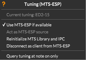
The Surge XT Tuning menu in MTS-ESP mode.
The MTS-ESP in parentheses at the top indicates that an MTS-ESP Source is present.
-
Current tuning - Displays the name of the currently active tuning in MTS-ESP.
-
Act as MTS-ESP source - When this option is checked, the current instance of Surge XT will become the MTS-ESP source. Any SCL/KBM loaded (or any changes applied from the Tuning Editor) in the current instance, will be applied to any MTS-ESP compatible instruments present, for example into all other instances of Surge XT (provided the “Use MTS-ESP…” option above was checked). The MTS-ESP specification only allows one source to exist at a time, so this option will be grayed out if another source is already present.
-
Re-Initialize MTS-ESP Library and IPC - Since there can only be one MTS-ESP source at a time, it’s important that sources properly de-register themselves when closing. If that doesn’t happen (say if the host crashes), that can lead to some problems. Pressing this button and re-starting your host session should solve these.
-
Disconnect as client from MTS-ESP - Provides a way to disable MTS-ESP in the current Surge XT instance, even when a Source is present, whereupon the individual instance will return to SCL-KBM mode.
-
Query tuning at note on only - This option is only relevant if you’re using an MTS-ESP source which can change tunings on-the-fly, like for example ODDsounds MTS-ESP Master. If the MTS-ESP tuning changes while notes are held, a client can choose whether to adjust those notes immediately (which will sound like pitch bends) or to wait until the next note-on. The former behavior (known as Dynamic Microtuning, the default for Surge XT), can enable some unheard-of musical gestures like morphing gradually from one tuning to the next. That may not always be what you want though, which is why this option exists. With it enabled, held notes keep their pitch when the tuning changes.
Main Menu
You can find this menu in the bottom-right corner of Surge XT’s interface. Clicking it reveals various configuration options.
Note: Some of these options are also present at the top of the user interface for easier access (see Status Area).
This menu can also be opened by right-clicking anywhere on the user interface where there are no controls.
Zoom
The Zoom option can be extremely useful on certain monitors and configurations.
In its sub-menu there are various options to change the scale of the whole user-interface to a certain size. Keep in mind that it will not let you change it to any size, as there is an upper limit depending on your screen resolution.
When a new instance of Surge is loaded, its zoom will be set to default size. To change this value, go back in this sub-menu and select the option “Set [zoom %] as default”, or “Set default zoom to …” then enter the desired value.
Skins
This is where the UI skin can be chosen. Surge XT comes with two factory skins: Classic and Dark.
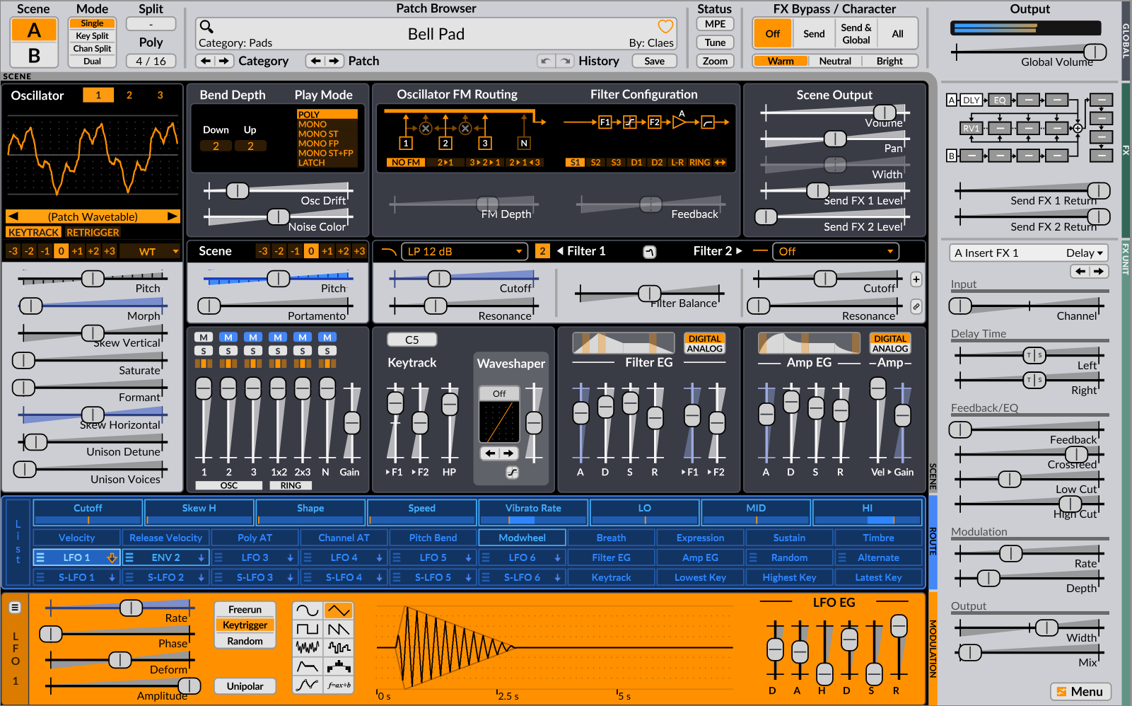
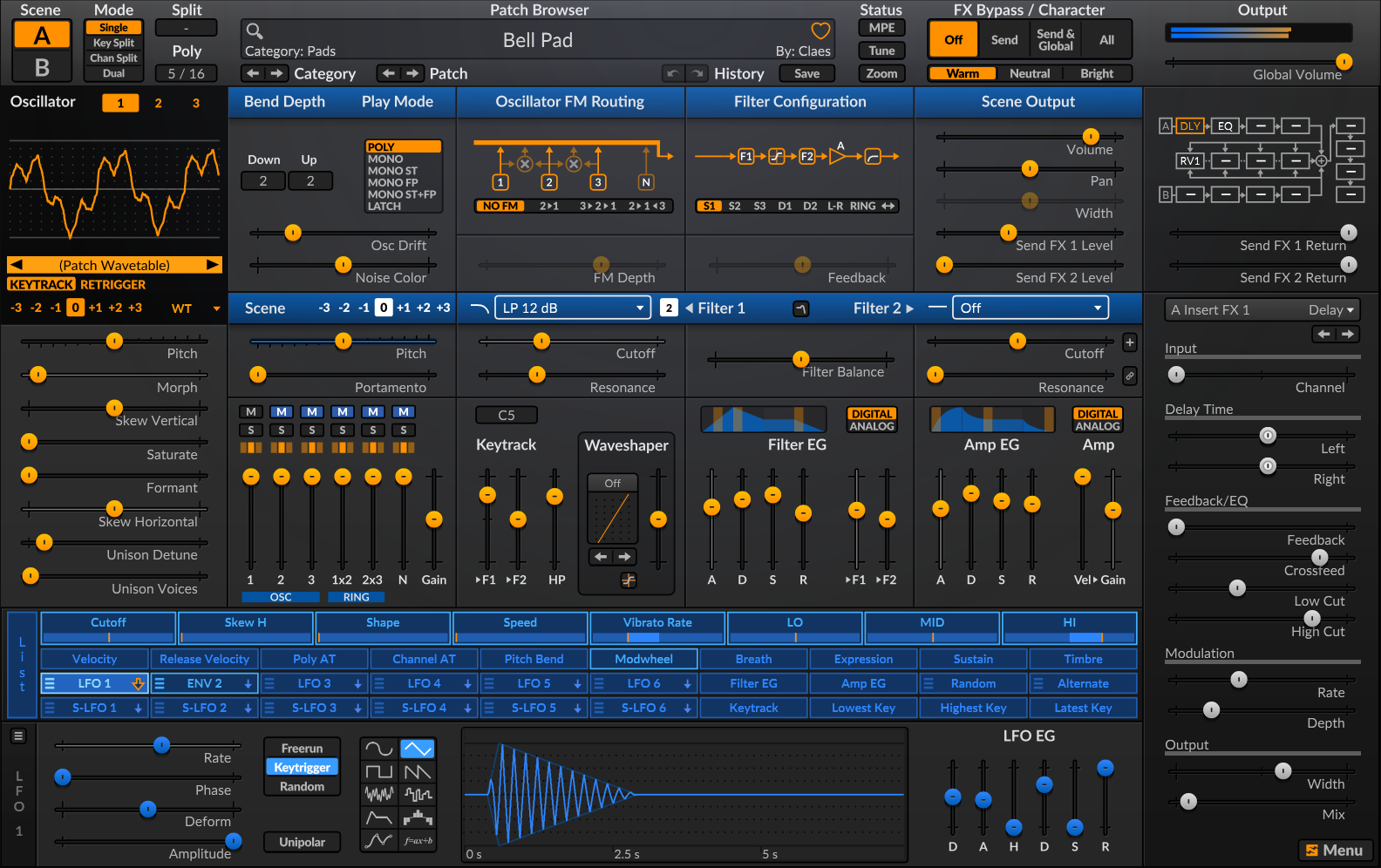
Additional skins are available to download from our skin library. Here is one of them, the Royal skin by Voger Design:
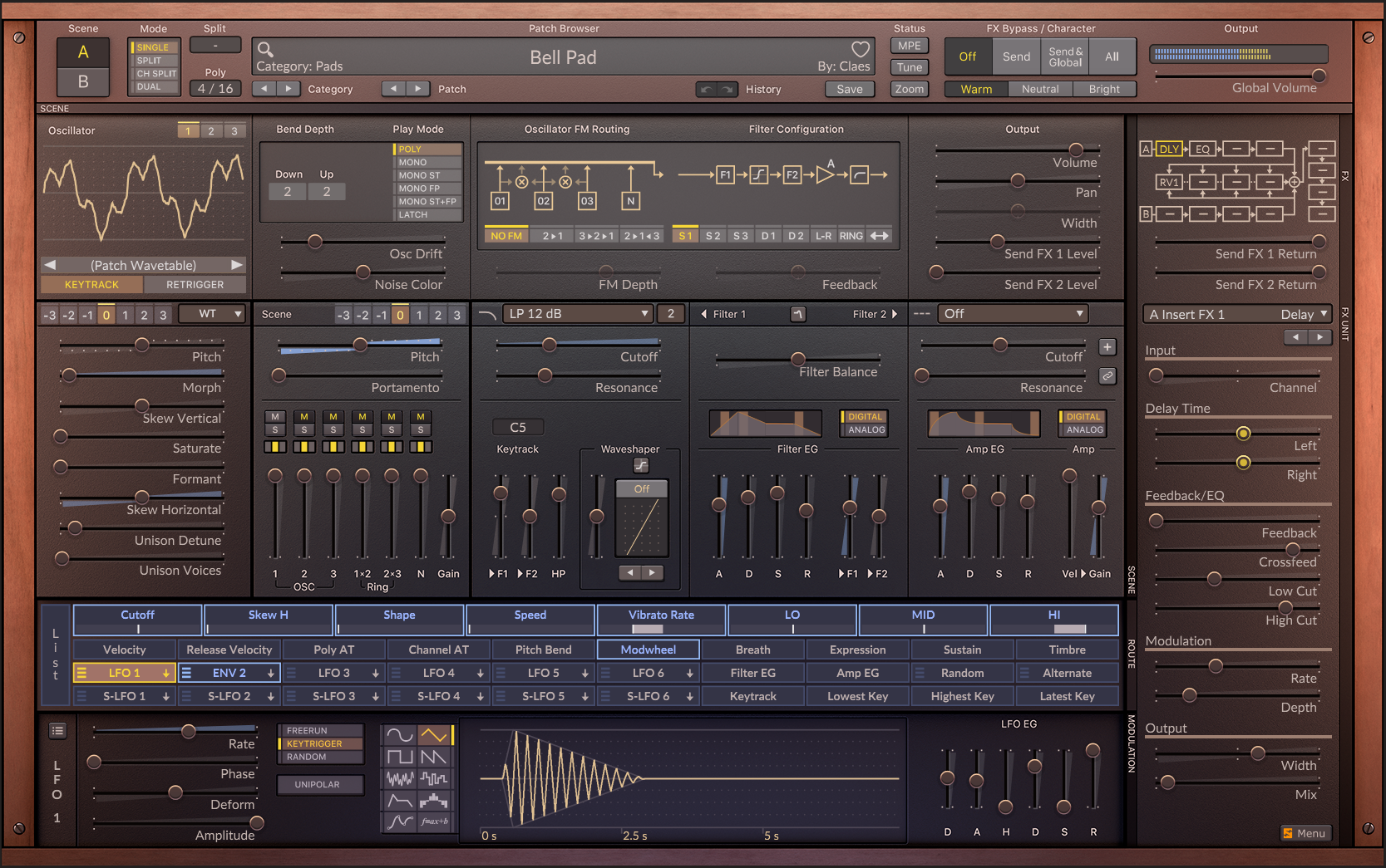
From there you can also reload the current skin and rescan the skins folder. You can even configure if the colors of context menus follow the OS light/dark mode settings, or are applied from the currently loaded skin.
From there, you can also reload the current skin, rescan skins, open the current skin folder location, open the skin inspector and open the skin development guide.
If you would like to get on board with the skin engine and developing skins, see the documentation on developing Surge XT skins.
Value Displays
-
High Precision Value Readouts - Allows value popups that appear when tweaking parameters to show more digits after the decimal point (6 digits). This can be useful in some more advanced and precise scenarios.
-
Modulation value readout shows bounds - Allows the value popup that appears when applying modulation and adjusting its amount to a parameter to show more values, such as the relative range in the negative direction, and both absolute minimum and maximum values underneath.
-
Show value readout on mouse hover - Allows you to enable or disable the gesture of hovering over a slider to display its value.
-
Show ghosted LFO waveform reference - Allows you to enable or disable the LFO waveform at full amplitude displayed with a dotted line in the LFO display area.
-
Middle C - Allows you to change the reference octave shown in popup displays of some frequency-related parameters, such as filter cutoff for instance. You can change Middle C to display either C3, C4 or C5.
Data Folders
In this sub-menu, there are a couple of options regarding user data and patches.
Open factory data folder… - This opens the location where factory patches, wavetables and other configuration files are stored.
Open user data folder… - This option opens the location where custom patches saved by the user will be stored.
Set custom user data folder… - This allows you to change where user patches will be saved.
Rescan all data folders - This option can be useful after importing patches created by someone else, after transferring user patches to another computer, or after downloading patches from the internet.
Mouse Behavior
This sub-menu contains options allowing you to change the sensitivity of the mouse when moving sliders. While Legacy is used by default, the other 3 options range from Slow (more granular) to Exact (as fast as the mouse pointer). Also, there is an option to keep showing the mouse pointer on the screen when dragging on a control.
Touchscreen mode automatically sets the mouse options to give the user the best experience when using Surge on a touch screen.
Patch Settings
This is where you can configure what appears by default in the Author and Comment fields when saving a patch.
You can also set the currently loaded patch as the default patch, append the original author
name to modified patches or not, and configure tuning and tuning mapping when loading patches.
Finally, there are options to export the currently loaded patch as an HTML file, either containing
all parameters, or only the ones that aren’t set to their default value.
Workflow
-
Remember tab positions per scene - Remember tab positions (for example, currently selected oscillator or LFO currently shown in the LFO editor) separately for each scene or unified in the whole synth.
-
Load MSEG snap state from patch - Tells Surge XT if it should load the MSEG snap parameters from the saved patch or keep the existing settings.
-
Previous/next patch constrained to current category - Turn this option off to allow the previous/next patch arrow buttons in the patch browser area to automatically switch categories after hitting the beginning or end of one.
-
Retain patch search results after loading - Prevents the search results box from closing after loading a searched patch. Useful if you want to preview all patches corresponding to your search query.
-
Confirm patch loading if unsaved changes exist - When this option is enabled, Surge XT will ask if you would like to save the currently edited patch before loading the next one.
-
Use keyboard shortcuts - Enables of disables the keyboard shortcuts.
-
Edit keyboard shortcuts… - Opens a window containing a list of all the available keyboard shortcuts in Surge XT. This is also where you can customize all those shortcuts and enable or disable them individually.
-
Shift + F10 and Edit parameter value shortcuts - If the first of the two options is enabled, the Shift + F10 keyboard shortcut and Enter key will allow you to access a control’s context menu. If the Follow mouse hover focus option is enabled, it will also follow the mouse cursor.
-
Virtual keyboard - Toggle this option to show or hide the virtual on-screen keyboard at the bottom of the user interface. The virtual keyboard also includes a pitch bend and modulation wheel control.
-
Oscilloscope… - This opens a window that displays an oscilloscope or a spectrum analyser. See Oscilloscope for more information.
Accessibility
-
Set all recommended accessibility options - Enables all the accessibility options found right below. Useful for quickly setting up Surge XT to work with screen readers.
-
Send additional accessibility announcements - Sends more information when using accessibility features, such as patch or category changes via the arrow buttons below the patch browser.
-
Announce patch browser entries - This is a Windows only option. If enabled, the narrator will announce the currently selected row in the patch browser.
-
Add sub-menus for modulation menu items - Makes the modulation options found in the context menu of controls work as a sub-menu with discrete Clear, Mute and Edit entries, alongside being able to directly click on the corresponding icons.
-
Focus modulator editor on “Add modulation from” actions - After using the context menu option “Add modulation from”, the modulator that is used to modulate the targeted control will be displayed in the modulation editor.
MPE Settings
MPE stands for MIDI Polyphonic Expression. It can be enabled or disabled in its sub-menu. The current and default pitch bend range can be changed here as well. Finally, you can also configure the MPE pitch bend smoothing amount.
MIDI Settings
This sub-menu contains options for MIDI mappings.
Controller Smoothing
This sub-menu contains options to set the amount of desired MIDI controller smoothing.
Sustain Pedal in Mono Mode
- Sustain pedal holds all notes (no note off retrigger) - If sustain is engaged and multiple notes are hit then held one after the other, Surge XT will stay on the latest note when releasing it instead of switching to the previous note.
- Sustain pedal allows note off retrigger - If sustain is engaged and multiple notes are hit then held one after the other, Surge XT will switch to the previous note when the latest note is released.
Use MIDI channels 2 and 3 to play scenes individually
Playing MIDI channels 2 or 3 when this option is unchecked will not play scene A or B individually.
Default Channel For Menu-Based MIDI Learn
This sub-menu contains options to choose which MIDI channel will be used by default when using the “Assign to MIDI CC” context menu option.
Soft Takeover MIDI Learned Parameters
Avoids sudden parameter jumps that can happen if received MIDI CC values are different from the current value of the assigned parameter. When this option is enabled, the assigned parameter will not be changed until a MIDI CC value is received that matches the parameter’s current value.
Save MIDI mapping as…
This allows you to save the current MIDI mapping. The newly created profile will appear in this menu under the two top options.
Set current MIDI mapping as default
When a new instance of Surge XT is opened, it will load this MIDI mapping by default if you select this option.
Clear current MIDI mapping
As its name suggests, this option clears the existing MIDI mapping in Surge XT and resets it back to default.
Show Current MIDI Mapping
This opens up an HTML file listing the currently loaded MIDI mapping.
OSC settings
Since version 1.3, Surge XT supports the Open Sound Control protocol. This sub-menu contains useful options related to OSC.
Show OSC Settings…
Selecting this option will open a small window containing the various settings related to OSC:
- OSC In: Allows you to change the port used for incoming OSC data. The currently used port is displayed in parentheses. Click on Default Port to reset the input port to its default value.
- OSC Out: Allows you to change the port used for outgoing OSC data. The currently used port is displayed in parentheses. Click on Default Port to reset the output port to its default value.
- Out IP Address: Allows you to change the output IP address used for the OSC protocol. Click on Localhost to reset the output IP address to its default value (the loopback address).
- ?: Allows you to see this section of the manual or displays the OSC specification (see below).
Show OSC specification…
Clicking on this option will open a local page on your browser that will provide informations about the specific implementation of OSC in Surge XT, as well as some more general information and documentation about the OSC protocol.
Download TouchOSC template…
We also provide a TouchOSC template, and this option opens a download page to read about it and get it for yourself.
Tuning
These options are also present in the Tuning menu at the top of the interface. See Microtuning for detailed explanations on the tuning implementation within Surge XT.
Online Links
The following items are for reaching the developers and user feedback information, reading the code on GitHub, downloading additional content, visiting Skin Library, opening this user manual, and finally opening Surge’s website.
About Surge XT
Finally, there is an option to open the About pane containing various version, configuration and license information.
Developer Menu
When right-clicking on the Menu button, some more options for development and testing purposes appear in various sub-menus. Holding down Shift when right-clicking anywhere where there is no control will also display this Developer option sub-menu.
Oscilloscope
Surge XT offers a basic real-time waveform and spectrum display to help with your sound design. After opening the Oscilloscope window, you can choose between either a Waveform Display (oscilloscope) or Spectrum Display.
In both modes, you can select to view only the left or right stereo channels or both simultaneously using the L and R buttons towards the top-right of the display. If both are selected, the results are averaged between the two channels. If neither are selected, the scope will be frozen in its current position until a channel is selected.
Waveform Display
The waveform display is based on the well-known oscilloscope plugin s(M)exoscope. Big thanks to Bram@Smartelectronix for open-sourcing this useful tool!
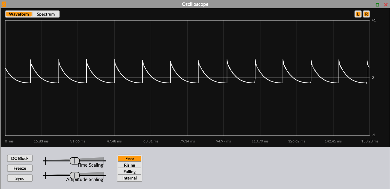
The oscilloscope has four trigger modes:
-
Freerun - Enabled by the default. The display never erases and immediately starts writing again at the left as soon as the waveform reaches the right side of the display area.
-
Rising Edge This mode retriggers the display every time a waveform peak rises past a certain level. This level is set with the Trigger Level slider. Drag this slider to set the retrigger level above or below the zero crossing. The retrigger level will be indicated by a horizontal white line on the display.
-
Falling Edge Identical to Rising mode, except that the display retriggers only when the waveform falls past the retrigger level.
-
Internal Trigger - Retriggers the display at a frequency set by the Internal Trigger Freq slider. Values are measured in Hz, and retrigger rates range from as infrequently as 0.441 Hz to as often as 139.4 times a second. This mode is useful if you only want to watch a certain part of a waveform.
In all of the above modes, the Retrigger Threshold slider determines how soon the display can be retriggered after the last trigger. This threshold is measured in samples, from 1 to 10000. For example, if the Retrigger Threshold is set to 450, then the display will not retrigger unless at least 450 samples have passed through the display since the last retrigger. This is useful if you absolutely need to see a certain number of samples in your waveform before it refreshes.
There are also two other sliders that control the display:
-
Time Scaling - Controls the number of pixels per sample. The lower the number, the finer the resolution of the waveform. When you change this slider, you can see the time scale marks on the display change to represent the new timescale.
-
Amplitude Scaling - Controls the amplitude of the waveform in the display. If your waveform appears too thin, turn it up. If your waveform is cut off at the top or bottom of the display, turn it down.
Finally, there are three options you can use to customize the oscilloscope’s behavior even further:
-
DC Block - Enabling this option will automatically compensate for DC offset, if your waveform is too far off the zero crossing line for example.
-
Freeze - This button can be used to freeze the waveform on the display.
-
Sync Redraw - When activated, Surge XT will only update waveform data when the plugin’s internal graphic buffer is full (as opposed to in real-time). In other words, turn this on to slow down how often the display refreshes, and adjust the Time Scaling slider again to find the right speed.
Spectrum Display
The spectrum display provides a simple instantaneous view of the frequency domain of the current synthesizer output. It is done using FFT, with a fixed block size of 8192 samples.

The display is updated with new data extremely quickly as it streams in. It interpolates between the prior FFT block and the new block over the course of (8196 / sample size) seconds. Once this very brief smoothing period passes, all new data is displayed.
The spectrum display can be controlled by a few parameters:
-
Min Level - Controls the lowest value that the display will show. Increase it in order to scale the display to your taste or your data.
-
Max dB - Controls the highest value that the display will show. Decrease it in order to scale the display to your taste or your data.
-
Decay Rate - Controls the time it takes for the spectrum’s amplitude to decay after a decrease in amplitude.
-
Freeze - This button can be used to freeze the spectral content on the display.
Accessibility
The Surge XT user interface can be completely navigated from the keyboard. Pressing Tab will allow you to move through all controls in the user interface, while pressing the up and down arrow keys will let you adjust them. Just like holding Shift or Ctrl/Command while moving a slider with the mouse lets you make more precise adjustments, holding these modifiers while pressing the arrow keys will have a similar effect. Pressing Home, End or Delete will let you set a control to its maximum, minimum and default value respectively. Finally, pressing Shift + F10 or the Applications key on any control will open its right-click menu.
With the exception of Tab, the other keys mentioned here need to be turned on before they can be used. If you press one of these keys with the shortcuts turned off, you will be asked whether you want to turn them on. Alternatively, they can be turned on by checking the Use keyboard shortcuts option in the Workflow section of the menu. A number of additional shortcuts are available which allow you to quickly open specific dialogs, change patches or save your work and more.
In addition to full keyboard support, Surge XT is compatible with screen reader software on both Mac and Windows. This means that as you navigate through the interface, the screen reader will give you full speech and braille feedback on the control that’s focused and what its value is. You can also navigate the interface using your screen reader’s review commands.
For additional help on using Surge with specific Screen Readers, refer to this page.
Technical Reference
Surge XT Hierarchy
Overview
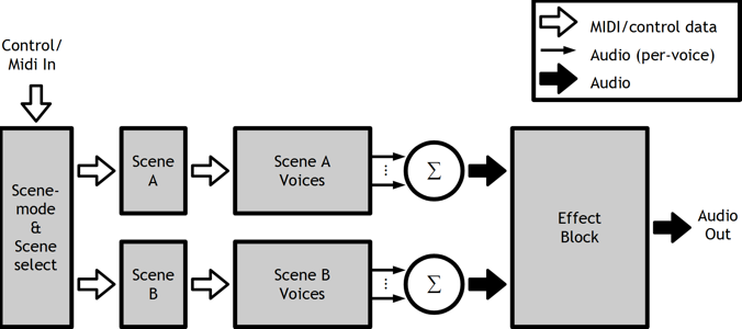
Block diagram of the synthesizer engine.
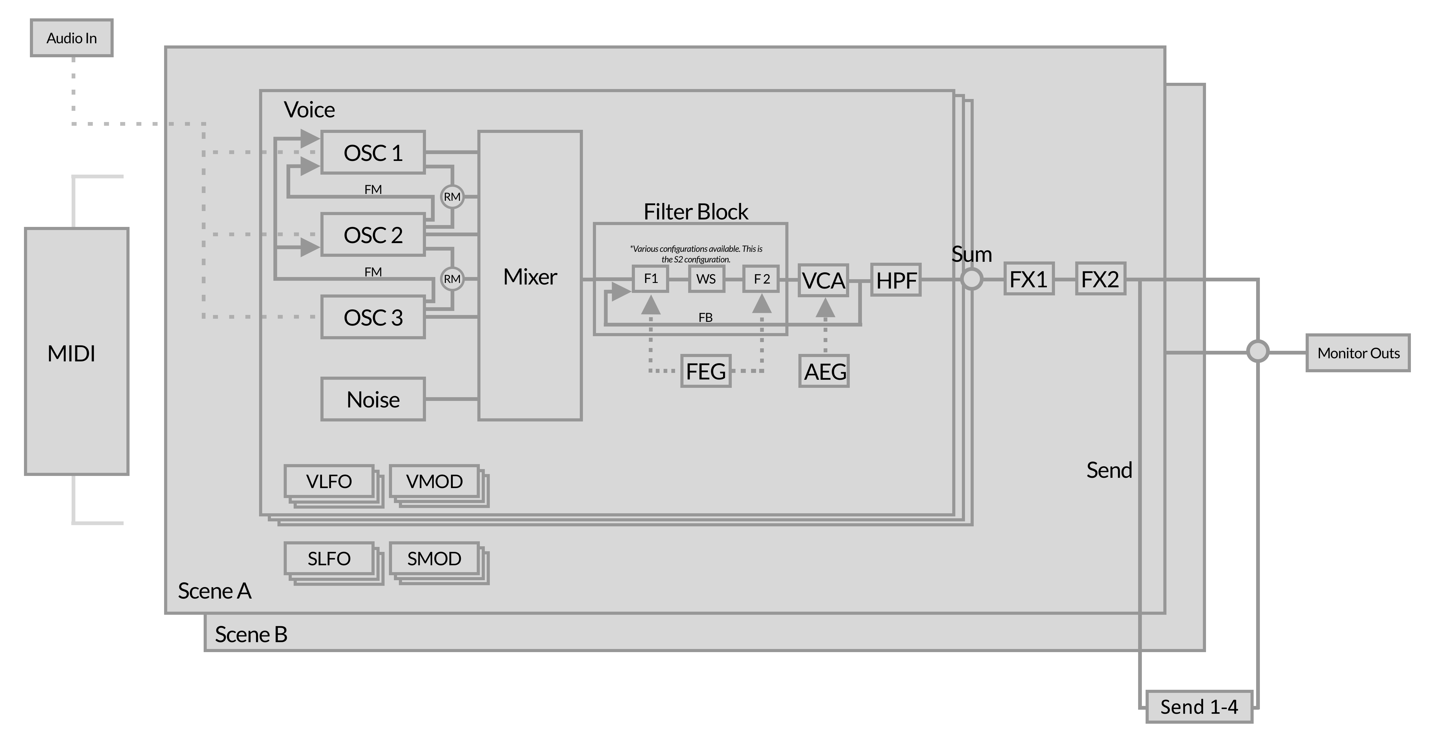
Illustration shows an overview of the synthesizer engine of Surge XT.
Voices
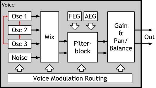
Block diagram of a synthesizer voice
Illustration shows most audio and control-paths of a single voice. Not all processing elements of the voice are shown in the diagram.
LFOs
Each voice has 6 configurable LFOs and each scene has an additional 6 configurable LFOs, making each voice effectively capable of receiving modulation from a total of 12 LFOs.
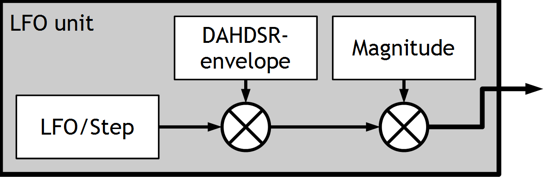
LFO block diagram
Modulation Routing Details
How the modulation routing works internally isn’t something you normally have to think about when using Surge XT. Just activate the modulation mode with the desired source and see which of the sliders that become blue. Nonetheless, it is useful to know which limitations are present and why.
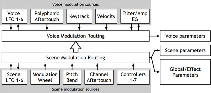
Modulation routing behind the scenes
The thing to remember is that voice modulation sources can’t modulate scene parameters, global/effect parameters or parameters from scene LFOs, since these are two distinctly different modulation paths. Other than that it should be pretty straightforward.
Oscillator Algorithms
Surge XT provides 12 different oscillator algorithms, each capable of generating sound in different ways with a different set of controls. They’re not just different waveforms.
Classic
The Classic oscillator algorithm consists of a main oscillator that can generate a pulse wave, a sawtooth wave, a dual-saw wave or anything in between.
A sub-oscillator provides a pulse-wave one octave below the main oscillator. Changing the pulse-width of the sub-oscillator does affect the main oscillator as well, as they will both change levels at the same time except that the main oscillator does it twice as often.
The Classic algorithm is also capable of oscillator self-sync. Note that the sub-oscillator will be used as the base-pitch for the sync.
The algorithm provides unison at the oscillator-level with up to 16 instances. Unlike the Wavetable oscillator, the cost of unison in terms of CPU usage for the Classic oscillator is quite modest. The unison oscillator voices are affected by the scene level Osc Drift parameter independently.
| Shape | Waveform shape. -100% = pulse, 0% = saw, 100% = dual saw. | -100 .. 100 % |
| Width 1 | Duty cycle (pulse) or relative phase (dual saw). | 0 .. 100 % |
| Width 2 | Squeezes or expands the waveform in a different way. If positive, the two latter halves of two consecutive single cycles get squeezed closer together. | 0 .. 100 % |
| Sub Mix | Sub-oscillator mix, 0% = only main, 100% = only sub. | 0 .. 100 % |
| Sync | Oscillator hard sync. | 0 .. 60 semitones |
| Unison Detune | Detuning of unison oscillators. Can be extended. Can be switched between relative (default) and absolute. | 0 .. 100 cents 0 .. 1200 cents 0 .. 16 Hz 0 .. 192 Hz |
| Unison Voices | Number of oscillators used for unison (1 = disabled). | 1 .. 16 |
Modern
The Modern oscillator algorithm is a multi-waveform oscillator which creates pulse, triangle, saw and sine waveforms with unison and sub-oscillator capabilities. It is based on the differentiated polynomial waveform algorithm, from this paper. The pulse, triangle and sawtooth waveforms are clean and result in very low aliasing, while the sine produces some additional harmonics.
Three parameters labeled Sawtooth, Pulse and Triangle control relative mixes of those waveforms, while the Width parameter controls the pulse width for the Pulse wave. Sync offsets the pitch of the oscillator against the pitch of the internal reference oscillator while resetting the phase of the main oscillator to the phase of the reference oscillator, to achieve typical hard sync effects. Unison controls work like in other Surge XT oscillators.
| Sawtooth | Amplitude of the Sawtooth waveform. | -100 .. 100 % |
| Pulse | Amplitude of the Pulse waveform. | -100 .. 100 % |
| Triangle/Sine/Square | Amplitude of the third waveform, can be right-clicked (for more information, see below this parameter list). | -100 .. 100 % |
| Width | Duty cycle of the Pulse waveform. | 0 .. 100 % |
| Sync | Oscillator hard sync. | 0 .. 60 semitones |
| Unison Detune | Detuning of unison oscillators. Can be extended. Can be switched between relative (default) and absolute. | 0 .. 100 cents 0 .. 1200 cents 0 .. 16 Hz 0 .. 192 Hz |
| Unison Voices | Number of oscillators used for unison (1 = unison disabled). | 1 .. 16 |
Third Waveform Parameter
The third waveform parameter (labeled “Triangle” by default) is special in that it has several waveform options to choose from. If you right-click it, you can see that it can generate a triangle wave, a sine wave, or a square wave. This control can also become a sub-oscillator, playing at half the frequency of the other two waveforms. Importantly, in sub-oscillator mode, the third waveform does not participate in unison, which is in contrast to the Sub Mix parameter in Classic oscillator. Finally, there is also an option for the sub-oscillator to bypass hard syncing against the internal reference oscillator.
Wavetable
A wavetable in Surge XT consists of up to 512 single-cycle waveforms (frames), each of which can consist of up to 4096 samples. Using the Morph parameter it is possible to sweep across the waveforms in the wavetable.
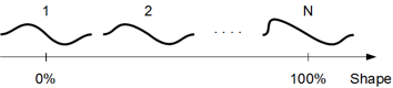
The individual waves are equidistant in the table. When the shape setting is between two individual waves, they will be mixed to ensure smooth travel. You can’t edit the wavetable contents directly within Surge XT, but it is possible to generate custom wavetables with external software.
Surge XT can also import wavetables containing a clm block to indicate loop size (as used by Serum), a cue block (as used by various products including Native Instruments) and a smpl block. Wavetable files without loop information are loaded as one-shots.
This effectively lets you import various wavetables from other products such as Serum. All those 3rd party wavetables that have been tested in Surge XT have been reported to work flawlessly.
To import custom wavetables, use the wavetable selection bar at the bottom of the oscillator display. This is where you can also download additional wavetable content.
Alternatively, you can simply drag-and-drop any compatible wavetable file anywhere over the Surge interface to load it.
You can even create your own wavetables for Surge using wt-tool or WaveEdit.
Once a wavetable is loaded, you can also export it using the wavetable selection bar.
Then, by modulating the Morph parameter, it is possible to create motion, dynamic response to playing and sonic variation. If you want to select an exact frame, drag the slider while holding down Ctrl/Command, which allows you to snap to exact values in the table, useful for switching between distinct shapes, for example.
What real-life property, if any, the Morph parameter is supposed to mirror depend on each wavetable. Common cases are:
- Analyzed from sounds that evolve over time. The behavior can be recreated by letting shape increase over time by modulation. It’s the most common among the analyzed wavetables.
- Analyzed from static sounds over different pitches to capture the formant shift of a sound. The behavior can be recreated by modulating shape by the keytrack modsource.
- A parameter of a mathematical equation.
In the end it’s just a set of data and Surge XT doesn’t care how it was generated, all that matters is how it sounds.
The Wavetable oscillator has some interesting sonic characteristics. It outputs the waveform in a stair-stepped fashion, making no attempts to ‘smooth the steps’ in the process, but does so in a manner that is completely band-limited. This makes it similar in sound to 1980s era wave-table synths and samplers which didn’t use resampling but had dedicated D/A-converters for each voice instead and changed the pitch by varying the sample rate of the individual D/As.
The fact that the steps aren’t smoothed causes an artifact known as harmonic aliasing. This is not to be confused with inharmonic aliasing which sounds somewhat similar to an AM-radio being tuned and is generally nasty. Instead, this artifact will cause the harmonics of the waveform to repeat themselves and fill up the entire audible spectra even at low pitches, just like a square-wave would, preventing the waveform from sounding dull. As this artifact is completely harmonic it is also musically pleasing. Nonetheless, it may sound a bit out of place on very smooth waveforms but the effect can be filtered out by a lowpass filter in the filter block if desired. Some of the wave-tables, such as the regular triangle wave, are large enough for this artifact to never appear in the normally used range for this specific reason.
The important thing is that just like most other oscillators in Surge XT, it doesn’t output any inharmonic aliasing whatsoever or any audible levels of interpolation-noise, two artifacts which has played a big part in giving digital synthesizers a bad name.
For more information, you can read this article on Surge’s wiki.
For developers and advanced users:
There is a reference for the .wt file-format used by the wavetables. It
is located at: surgedata/wavetables/wt fileformat.txt
| Morph | Interpolates between wavetable frames. 0% = first frame, 100% = last frame. Can be set to non-continuous. | 0 .. 100 % |
| Skew Vertical | Vertical skew of the waveform. | -100 .. 100 % |
| Saturate | Soft saturation of the waveform. | 0 .. 100 % |
| Formant | Compresses the waveform in time but keeps the cycle-time intact. | 0 .. 60 semitones |
| Skew Horizontal | Horizontal skew of the waveform. | -100 .. 100 % |
| Unison Detune | Detuning of unison oscillators. Can be extended. Can be switched between relative (default) and absolute. | 0 .. 100 cents 0 .. 1200 cents 0 .. 16 Hz 0 .. 192 Hz |
| Unison Voices | Number of oscillators used for unison. 1 = disabled. | 1 .. 16 |
Window
The Window oscillator is another shot at wavetable synthesis that is quite different from the previous wavetable algorithm.
The wave, which can be any wavetable included with Surge XT, is multiplied by a second waveform, the window, which can be one of 9 waveform types that are specifically made for the window oscillator. The formant parameter controls the pitch of the wave independently of the window, but as the wave is always restarted with the window, the pitch will remain the same. Instead, the timbre of the sound will change dramatically, much depending on which window is selected.
Unlike the Wavetable algorithm, the Window oscillator uses a more traditional resampling approach which doesn’t result in harmonic aliasing.
| Morph | Selects a frame from the wavetable, without interpolation. 0% = first frame, 100% = last frame. Can be set to continuous. | 0 .. 100 % |
| Formant | Adjusts pitch of the wavetable frame, independently from the pitch of the window. | -60 .. 60 semitones |
| Window | Chooses the waveform used for the amplitude window. | Triangle, Cosine, Blend 1, Blend 2, Blend 3, Sawtooth, Sine, Square, Rectangle |
| Low Cut | Cutoff frequency of built-in highpass filter. Must be activated in context menu. | 13.75 .. 25087.71 Hz |
| High Cut | Cutoff frequency of built-in lowpass filter. Must be activated in context menu. | 13.75 .. 25087.71 Hz |
| Unison Detune | Detuning of unison oscillators. Can be extended. Can be switched between relative (default) and absolute. | 0 .. 100 cents 0 .. 1200 cents 0 .. 16 Hz 0 .. 192 Hz |
| Unison Voices | Number of oscillators used for unison. 1 = disabled. | 1 .. 16 |
Sine
Quite unsurprisingly, this oscillator generates a sine waveform. However, there’s a number of other interesting things this oscillator can do!
| Shape | Various variants of sine wave achieved through quadrant masking, shifting and frequency doubling. | 1 .. 28 |
| Feedback | FM feedback amount. Can be extended. Can be set to Vintage FM (smoother feedback). | -100 .. 100 % -400 .. 400 % |
| FM Behavior | Chooses whether FM behaves like Surge 1.6.1.1 and earlier, or consistent with FM2/3 oscillators. | Legacy (before v1.6.2), Consistent with FM2/3 |
| Low Cut | Cutoff frequency of built-in highpass filter. Must be activated in context menu. | 13.75 .. 25087.71 Hz |
| High Cut | Cutoff frequency of built-in lowpass filter. Must be activated in context menu. | 13.75 .. 25087.71 Hz |
| Unison Detune | Detuning of unison oscillators. Can be extended. Can be switched between relative (default) and absolute. | 0 .. 100 cents 0 .. 1200 cents 0 .. 16 Hz 0 .. 192 Hz |
| Unison Voices | Number of oscillators used for unison, 1 = disabled. | 1 .. 16 |
FM2
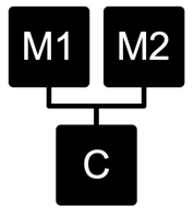
FM2 provides a miniature FM synthesizer voice in an oscillator that is specifically tailored towards making nice and musical FM sounds. A single sine carrier is modulated by two sine modulators, whose ratios to the carrier are always integer thus the resulting waveform is always cyclic. However, M1/2 Offset lets you offset the modulators slightly in an absolute fashion, creating an evolving and pleasing detune effect.
| M1 Amount | Modulation amount of the first modulator | 0 .. 100 % |
| M1 Ratio | Ratio of the first modulator to the carrier | 1 .. 32 |
| M2 Amount | Modulation amount of the second modulator | 0 .. 100 % |
| M2 Ratio | Ratio of the second modulator to the carrier | 1 .. 32 |
| M1/2 Offset | Absolute detuning of the modulators Can be extended. | -10 .. 10 Hz -1000 .. 1000 Hz |
| M1/2 Phase | Changes the initial phase of the modulators to give different variations of the waveform. | 0 .. 100 % |
| Feedback | Modulation amount of the carrier to itself Extended mode (default) can be disabled. Can be set to Vintage FM (smoother feedback). | -400 .. 400 % -100 .. 100 % |
FM3
As a contrast to FM2, FM3 is the algorithm of choice for scraping paint off the walls. The modulators have a larger range, the ratios can be non-integer and there’s a third modulator which has its rate set as an absolute frequency.
| M1 Amount | Modulation amount of the first modulator | 0 .. 100 % |
| M1 Ratio | Ratio of the first modulator to the carrier, can either be extended or absolute. | 0.0 .. 32.00 1/32.0 .. 32.0 ~ 8 Hz .. 24 kHz |
| M2 Amount | Modulation amount of the second modulator | 0 .. 100 % |
| M2 Ratio | Ratio of the second modulator to the carrier, can either be extended or absolute. | 0.0 .. 32.00 1/32.0 .. 32.0 ~ 8 Hz .. 24 kHz |
| M3 Amount | Modulation amount of the third modulator | 0 .. 100 % |
| M3 Frequency | Frequency of the third modulator | ~ 14 Hz .. 25 kHz 0.5 Hz .. ~25 kHz |
| Feedback | Modulation amount of the carrier to itself Extended mode (default) can be disabled. Can be set to Vintage FM (smoother feedback). | -400 .. 400 % -100 .. 100 % |
String
The String oscillator uses a physical modeling technique where excitation sources are sent into a tuned delay line with feedback, with various filters inline (based on the original Karplus-Strong algorithm). The oscillator runs two strings at all times which can be detuned from each other and individually damped.
To make the model create sound, you need to excite it. We have two classes of excitation modes, Burst and Constant. In Burst mode, the delay line is loaded with a pattern before a note is played, and then no further signal is added to the oscillator. Think of this as emulating a plucked string. In Constant mode, the delay line is also pre-loaded, but the signal continues to be applied for as long as you hold the key. Think of this as emulating a bowed string. In almost all cases, Continuous excitation modes would be used along with modulation of Exciter Level parameter, in order to emulate bow pressure, and so on.
Exciter modes provide various waveforms - noise, pink noise, ramp, etc. - which you can use to excite the strings, leading to different timbres. Surge XT’s audio input can also be used as an exciter signal!
| Exciter | Determines mode and waveform used to excite the string. | Burst, Constant |
| Exciter Level | Determines how strongly the string gets excited. Oversampling and interpolation can be configured in its context-menu. | -100 .. 100 % |
| String 1 Decay | Sets the decay time of the first string (amount of delay line feedback). | -100 .. 100 % |
| String 2 Decay | Sets the decay time of the second string (amount of delay line feedback). | -100 .. 100 % |
| String 2 Detune | Adjusts tuning of the second string. Can be extended. Can be switched between relative (default) and absolute. | -100 .. 100 cents -1200 .. 1200 cents -16 .. 16 Hz -192 .. 192 Hz |
| String Balance | Adjusts mix between the two strings. | -100 .. 100% |
| Stiffness | Applies lowpass (left) and highpass (right) filters in the feedback loop. Results in inharmonic timbres at the extremes. The stiffness filter can be configured in its context-menu. | -100 .. 100% |
Twist
This oscillator imports a rather famous Eurorack macro oscillator into Surge XT, based on Émilie Gillet’s device. You can read the manual for the hardware module on which this oscillator is based here.
This implementation presents all 16 oscillator modes and the controls are dynamically renamed appropriately for every model. Core differences between the hardware module and Surge XT’s implementation are:
-
By default, the LPG in the module is disabled, but by activating the LPG level and decay sliders with (right-click, then Activate), the LPG will be triggered per voice for each received MIDI note.
-
By default, you can mix between the main and the auxiliary oscillator outputs with the Mix parameter. You can also right-click the Mix parameter and enable Pan main and auxiliary signals option, in which case -100% value is Main to left/Aux to right, +100% is Main to right/Aux to left, and 0% is an even mix of both signals sent to both left and right. Do note that for this to be audible, you have to be in one of stereo filter configuration modes.
Twist can be more CPU demanding than most other Surge XT oscillator algorithms. Judiciously using maximum polyphony setting and being careful with Amp EG release times can go a long way in minimizing the CPU usage, thus making robust patches.
Alias
The Alias oscillator purposefully ignores a few decades of research into making digital signals with low or no aliasing, and does all the things you shouldn’t do, so it purposefully sounds digital, gross, broken, terrible, yet awesome all at once.
| Shape | Sets the oscillator waveform. | See explanation below |
| Wrap | Mangles the waveform by amplifying it, then making it wrap around from the other side instead of hard clipping. | -100 .. 100 % |
| Mask | Sets a 8-bit bitmask applied to the waveform. | -100 .. 100 % |
| Threshold | Adjusts the turning point (ramp), duty cycle (pulse) or wavetable readout offset (others) of the waveform. | -100 .. 100 % |
| Bitcrush | Sets the amount of bitcrushing applied to the waveform. | 1.00 .. 8.00 bits |
| Unison Detune | Detuning of unison oscillators. Can be extended. Can be switched between relative (default) and absolute. | 0 .. 100 cents 0 .. 1200 cents 0 .. 16 Hz 0 .. 192 Hz |
| Unison Voices | Number of oscillators used for unison, 1 = disabled. | 1 .. 16 |
Shape
Shape parameter (comes in the form of a menu) is very important and is worth explaining in more detail, as it allows you to choose the source used for the Alias algorithm.
In addition to the more regular shapes (such as Sine, Ramp, Pulse and Noise), Surge XT’s audio input can be also used.
Going further, there is Additive, which allows you to create a custom waveform by adjusting amplitudes of up to 16 harmonics, accessible by clicking on the Edit button that appears in this mode:
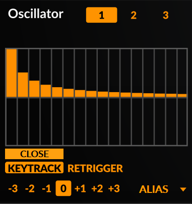
This editor works in a similar way to the step sequencer editor, however there are some additional options available when right-clicking:
- Shapes - Partial level presets which roughly represent different wave shapes, including a random option.
- Absolute - Sets the level of all the partials in the positive range.
- Invert - Flips the partial levels vertically.
- Reverse - Flips the partial levels horizontally.
Additionally, you can also use Quadrant Shaping waveforms as a source, which are also found in the Sine oscillator.
Finally, we have various Memory from… options:
- This Alias Instance - Generates a waveform based on reading memory associated with the currently selected instance of Alias.
- Oscillator Data - Generates a waveform based on reading memory associated with general oscillator data.
- Step Sequencer Data - Generates a waveform based on reading memory associated with step sequencer data.
- Scene Data - Generates a waveform based on reading memory associated with general scene data.
- DAW Chunk Data - Generates a waveform based on reading memory that serves as additional DAW chunk data (various non-automatable parameters and settings).
Note: When using Memory From… as a source, there is no guarantee that the resulting waveform will be consistent, as memory data can vary depending on a number of things: the DAW used, the particular Surge XT instance, rebooting your machine, and so on. Thus, it’s good practice to bounce the audio output from Surge XT when using this mode. You know what they say; “If you like it, you should… put a mic on it.”
S&H Noise
S&H is an abbreviation for ‘Sample and Hold’. The S&H Noise oscillator algorithm works like a pulse oscillator, but instead of always switching between +1 and -1, the levels used are determined stochastically.
The correlation parameter determines how new levels are calculated. A setting of 0% will have no memory and each new level will effectively be a random number (white noise). A lower setting will favor new values that are closer to the previous level and will provide noise with a darker spectra. Higher values will favor values as far away from the previous one as possible, with 100% resulting in a harmonic pulse wave.
| Correlation | Noise correlation. 0% = white noise, 100% = pulse wave. | -100 .. 100 % |
| Width | Duty cycle of the oscillator. | 0 .. 100 % |
| Low Cut | Cutoff frequency of built-in highpass filter. Must be activated in context menu. | 13.75 .. 25087.71 Hz |
| High Cut | Cutoff frequency of built-in lowpass filter. Must be activated in context menu. | 13.75 .. 25087.71 Hz |
| Sync | Oscillator hard sync. | 0 .. 60 semitones |
| Unison Detune | Detuning of unison oscillators. Can be extended. Can be switched between relative (default) and absolute. | 0 .. 100 cents 0 .. 1200 cents 0 .. 16 Hz 0 .. 192 Hz |
| Unison Voices | Number of oscillators used for unison. 1 = disabled. | 1 .. 16 |
Audio Input
Audio Input lets you route external audio into the voice architecture of Surge XT. It also allows you to route the audio output from Scene A into Scene B.
| Audio In L/R Channel | Chooses which external input is used. -100% = left, 0% = both (stereo), 100% = right. | -100 .. 100 % |
| Audio In Gain | External input gain in dB. | 48 .. +48 dB |
| Scene A L/R Channel1 | Chooses which input from Scene A is used. -100% = left, 0% = both (stereo), 100% = right. | -100 .. 100% |
| Scene A Gain1 | Scene A input gain in dB. | 48 .. +48 dB |
| Audio In Scene A Mix1 | Blend control between the external audio-in signal and the output of Scene A. | -100 .. +100% |
| Low Cut | Cutoff frequency of built-in highpass filter. Must be activated in context menu. | 13.75 .. 25087.71 Hz |
| High Cut | Cutoff frequency of built-in lowpass filter. Must be activated in context menu. | 13.75 .. 25087.71 Hz |
1 Only available in Scene B
Note: When using the Audio Input oscillator type in Scene B to get audio from Scene A, you will likely want to set Play Mode to Latch. That way, Scene B will always be triggered.
For more information and possible applications, you can read this article on Surge’s wiki.
Filters
There are multiple filter algorithms available for each of the 2 filter units in the filter block. Each of the algorithms have different subtypes, which alter their sound.
Some of the filter-(sub)types have some non-linear elements in them to allow them to self-oscillate in a stable and predictable manner. This means they will sound different depending on how hard they’re driven, which can be conveniently controlled with the Pre-Filter Gain setting found in the mixer. For example, if the resonance peaks of a filter is too loud, increase the Pre-Filter Gain to make the rest of the signal more dominant (and if needed decrease the gain at the output stage of the voice to compensate).
Filters in Surge XT are divided into the following categories:
- Lowpass
- Highpass
- Bandpass
- Notch
- Multi
- Effect
Filter Types
12 dB - 2-pole filter. Available in Lowpass, Highpass, Bandpass and Notch types.
24 dB - 4-pole filter. Available in Lowpass, Highpass, Bandpass and Notch types.
Sub-types for both 12 dB and 24 dB:
- Standard - clear with a strong resonance, capable of self-oscillation. Handles transient behavior extremely well.
- Driven - chesty, somewhat distorted sound with a more held-back resonance. Capable of self-oscillation.
- Clean - the smoothest and cleanest sounding subtype, capable of lower resonance than the others, which is suitable when you do not want the sound of the filter to be noticed but only to roll-off a part of the spectrum.
Legacy Ladder - 4-pole ladder filter. This is Surge’s original and older ladder filter. It has stable self-oscillation and requires less CPU processing than the newer Vintage Ladder filter. Available in Lowpass type.
Sub-types:
- 6 dB - Output taken from 1st stage (1-pole).
- 12 dB - Output taken from 2nd stage (2-pole).
- 18 dB - Output taken from 3rd stage (3-pole).
- 24 dB - Output taken from 4th stage (4-pole).
Vintage Ladder - 4-pole ladder filter. This is a more recent, accurate and often better-sounding ladder filter. It also has stable self-oscillation, but requires more CPU processing than the older Legacy Ladder filter. Available in Lowpass type.
Sub-types:
- Type 1 - Imitates a Moog resonant filter by Runge-Kutta numerical integration of a differential equation approximately describing the dynamics of the circuit.
- Type 1 Compensated - Gain-compensated version of Type 1.
- Type 2 - Moog Ladder filter that builds upon the work done by Smith and Stilson from Antti Huovilainen’s paper.
- Type 2 Compensated - Gain compensated version of Type 2.
Thanks to @ddiakopoulos for maintaining this very useful repository of research and code which heavily informed the models we implemented.
K35 - 12 dB/Octave filters from the Odin 2 synthesizer, and inspired by the Korg MS-20 filter topology. Increasing resonance will make them sound dirtier and more aggressive. Available in Lowpass and Highpass types.
Sub-types:
- No Saturation
- Mild Saturation
- Moderate Saturation
- Heavy Saturation
- Extreme Saturation
Thanks to @TheWaveWarden for allowing us to implement Odin 2’s K35 filters inside Surge XT. You can download Odin 2 here, or read the code here.
Diode Ladder - 4-pole diode ladder filter from the Odin 2 synthesizer with individually tapped pole outputs. This filter attempts to model the sound of a ladder filter that uses diodes instead of transistors. This filter does not self-oscillate without feedback. Available in Lowpass type.
Sub-types:
- 6 dB - Output taken from 1st stage (1-pole).
- 12 dB - Output taken from 2nd stage (2-pole).
- 18 dB - Output taken from 3rd stage (3-pole).
- 24 dB - Output taken from 4th stage (4-pole).
Thanks to @TheWaveWarden for allowing us to implement Odin 2’s Diode Ladder filters inside Surge XT. You can download Odin 2 here, or read the code here.
OB-Xd 12dB - 2-pole filters from the OB-Xd synthesizer originally by Vadim Filatov (2DaT), which is based on the filters found in the Oberheim OB-Xa. Available in Lowpass, Highpass, Bandpass and Notch types.
Sub-types:
- Standard - Standard filter response.
- Pushed - Adds boosted non-linearities that drives the filter into more self-oscillation at high resonance values.
Thanks to discoDSP for allowing us to implement OB-Xd’s filters inside Surge XT. You can get OB-Xd here, or read the source here.
OB-Xd 24 dB - 4-pole filters from the OB-Xd synthesizer originally by Vadim Filatov (2DaT), which is based on the filters found in the Oberheim OB-Xa. Available in Lowpass type.
Sub-types:
- 6 dB - Output taken from 1st stage (1-pole).
- 12 dB - Output taken from 2nd stage (2-pole).
- 18 dB - Output taken from 3rd stage (3-pole).
- 24 dB - Output taken from 4th stage (4-pole).
Cutoff Warp - 2-pole filters created using a non-linear biquad filter structure. These non-linearities cause the cutoff frequency to sweep to higher frequencies as the signal level increases (see below). Available in Lowpass, Highpass, Bandpass, Notch and Allpass (Effect) types.
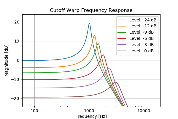
For more information on the Cutoff Warp filter, see this blog post by Jatin Chowdhury, or this 2020 DAFx paper, specifically section 4.
Resonance Warp - 2-pole filters created using a non-linear biquad filter structure. These non-linearities cause the resonance of the filter to decrease as the signal level increases (see below). Available in Lowpass, Highpass, Bandpass, Notch and Allpass (Effect) types.
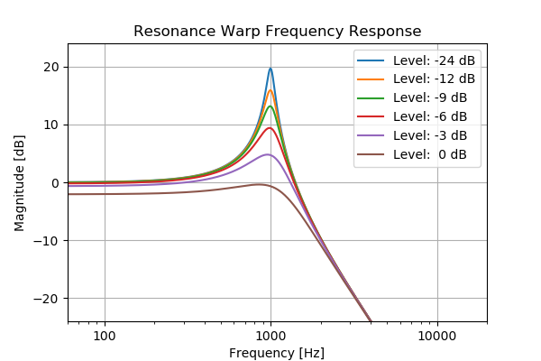
For more information on the Cutoff Warp filter, you can see this blog post by Jatin Chowdhury, or this 2020 DAFx paper, specifically section 3.
Sub-types for Cutoff Warp and Resonance Warp:
- 1 Stage tanh - Output taken from 1st stage (2-pole), using
tanhnon-linearities. - 2 Stages tanh - Output taken from 2nd stage (4-pole), using
tanhnon-linearities. - 3 Stages tanh - Output taken from 3rd stage (6-pole), using
tanhnon-linearities. - 4 Stages tanh - Output taken from 4th stage (8-pole), using
tanhnon-linearities. - 1 Stage Soft Clip - Output taken from 1st stage (2-pole), using soft-clipping non-linearities.
- 2 Stages Soft Clip - Output taken from 2nd stage (4-pole), using soft-clipping non-linearities.
- 3 Stages Soft Clip - Output taken from 3rd stage (6-pole), using soft-clipping non-linearities.
- 4 Stages Soft Clip - Output taken from 4th stage (8-pole), using soft-clipping non-linearities.
- 1 Stage OJD - Output taken from 1st stage (2-pole), using OJD non-linearities.
- 2 Stages OJD - Output taken from 2nd stage (4-pole), using OJD non-linearities.
- 3 Stages OJD - Output taken from 3rd stage (6-pole), using OJD non-linearities.
- 4 Stages OJD - Output taken from 4th stage (8-pole), using OJD non-linearities.
Tri-Pole - 3-pole filter based on the Threeler filter designed by Ian Fritz, which contains 3 filter stages and a resonance stage in a global feedback loop.
- Low -> Low -> Low, First - Output taken from the 1st filter stage.
Filter stages are: LPF, LPF, LPF. - Low -> High -> Low, First - Output taken from the 1st filter stage.
Filter stages are: LPF, HPF, LPF. - High -> Low -> High, First - Output taken from the 1st filter stage.
Filter stages are: HPF, LPF, HPF. - High -> High -> High, First - Output taken from the 1st filter stage.
Filter stages are: HPF, HPF, HPF. - Low -> Low -> Low, Second - Output taken from the 2nd filter stage.
Filter stages are: LPF, LPF, LPF. - Low -> High -> Low, Second - Output taken from the 2nd filter stage.
Filter stages are: LPF, HPF, LPF. - High -> Low -> High, Second - Output taken from the 2nd filter stage.
Filter stages are: HPF, LPF, HPF. - High -> High -> High, Second - Output taken from the 2nd filter stage.
Filter stages are: HPF, HPF, HPF. - Low -> Low -> Low, Third - Output taken from the 3rd filter stage.
Filter stages are: LPF, LPF, LPF. - Low -> High -> Low, Third - Output taken from the 3rd filter stage.
Filter stages are: LPF, HPF, LPF. - High -> Low -> High, Third - Output taken from the 3rd filter stage.
Filter stages are: HPF, LPF, HPF. - High -> High -> High, Third - Output taken from the 3rd filter stage.
Filter stages are: HPF, HPF, HPF.
For more information on the development of the Tri-Pole filter, see this Python notebook which outlines the development of the signal processing building blocks behind the filter.
Allpass - As its name suggests, this filter passes all frequencies equally in gain. However, it is useful to alter the phase relationship in the spectrum. Unless feedback is involved, its effect can mostly be heard when the Cutoff frequency is in movement. Thus, modulation can be used to get interesting results.
Allpass can be found under the Effect category.
Comb + and Comb - - Comb filter, which is different compared to the previous filter types since it doesn’t filter any part of the spectrum, but instead plays back the original signal with a delay. The former type has positive feedback and the latter has negative feedback.
Sub-types:
- 50% Wet
- 100% Wet
When the sub-type is set to 2 and resonance is 0%, the comb filter will work purely as a delay unit (with sub-sample precision). This can be used together with the other filter unit along with filter block feedback to provide interesting options. The “Winds/Clarinet” and ” Plucks/Simple Waveguide” patches showcase how this ability can be used for simple physical modeling. They only use the oscillator section to ignite the sound, the rest is in the filter block.
Moreover, the negative comb filter produces the sound an octave lower than the positive comb filter.
Comb + and Comb - can be found in the Effect category.
Sample & Hold - The Sample & Hold module will sample the audio at the rate set by the cutoff frequency. Resonance will emphasize oscillations around the cutoff frequency, not unlike the resonance peak of a lowpass filter.
Sample & Hold can be found in the Effect category.
Effects
Surge XT has 8 effect units which each can run one of the 10 provided algorithms.
EQ
The EQ unit provides 3-bands of fully parametric equalizing. This high-quality algorithm has a much better response at high frequencies than digital equalizers usually have.
| Band 1/2/3 Gain | Band gain, can be disabled | -48 .. +48 dB |
| Band 1/2/3 Freq | Band frequency | 14Hz .. 25kHz |
| Band 1/2/3 Bandwidth | Band bandwidth | 0 .. 5 octaves |
| Output gain | Gain control | -48 .. +48 dB |
| Mix | Blend control between the dry and the wet signal. | 0 .. 100 % |
Exciter
Exciter is a harmonic exciter based on the famous Aphex Aural Exciter unit. For more information, see this blog post by Jatin Chowdhury.
| Drive | Controls the amount of generated harmonics. | 0 .. 100 % |
| Tone | Controls the tone balance of the generated harmonics. | 0 .. 100 % |
| Attack | Controls the attack time of the generated harmonics. | 5 .. 20 ms |
| Release | Controls the release time of the generated harmonics. | 50 .. 200 ms |
| Mix | Controls the mix of wet and dry signals. | 0 .. 100 % |
Graphic EQ
Graphic EQ is, as its name suggests, a graphic equalizer. It is comprised of 11 level-adjustable and deactivatable (from the right-click menu) bands, which makes this equalizer better than the normal EQ at sculpting relatively complex response curves. Apart from the fact that there is also an output gain control at the bottom of the interface, there is not much else to add.
Resonator
The Resonator provides carefully tuned lowpass, bandpass, bandpass + notch or highpass filters, each with individual output gain and resonance. By default, the filters cannot be driven into self-oscillation, but if you right-click any of the three Resonance parameters and enable Modulation extends into self-oscillation, modulation sources can drive the filters to a self-oscillating point. Similarly, the three resonator bands are tuned to match the ranges of a very famous resonator circuit, but they can be extended to allow a wider range.
| Frequency 1/2/3 | Frequency of the filter for the the first, second or third band. Can be extended. | 60 .. 300 Hz 60 .. 7500 Hz |
| Resonance 1/2/3 | Amount of resonance for the first, second or third band. Modulation can be allowed to push the filter into self-oscillation from the right-click menu. | 0 .. 100 % |
| Gain 1/2/3 | First, second or third band gain. | -inf .. 0 dB |
| Mode | Sets the filter type used in the resonator effect. | Lowpass, Bandpass, Bandpass+Notch, Highpass |
| Mix | Controls the mix of wet and dry signals | 0 .. 100 % |
Bonsai
Bonsai is an organic-sounding distortion effect, combining a highly non-linear bass boost with an emphasis-filtered waveshaper and noise AM. It excels at a wide range of very beefy gnarly sounds, but can sound very good at subtle settings too.
| Input Gain | Controls the input gain coming in the Bass Boost section. | -24dB .. 24dB |
| (Bass Boost) Amount | Controls the amount non-linear bass boosting. | -24dB .. 24dB |
| (Bass Boost) Distort | Controls the amount of distortion applied to the bass bosting. | 0 .. 100 % |
| (Saturation) Bias Filter | Determines which filter curve and counter-curve to apply pre and post-saturation, respectively. | Tilt, Pull Mids |
| (Saturation) Type | Allows you to select the type of saturation applied. | Gentle, Normal, Hard, Harsh |
| (Saturation) Amount | Controls the amount of saturation applied. | 0 .. 100 % |
| (Noise) Sensitivity | Controls the threshold from which noise will be introduced after the distorted signal path. | 0 .. 100 % |
| (Noise) Gain | Controls the noise output gain. | -24dB .. 24dB |
| (Output) Dull | Applies a bandpass filter on the output to taim the low and high frequencies. | 0 .. 100 % |
| (Output) Mix | Controls the mix of wet and dry signals. | 0 .. 100 % |
CHOW
Chow is a half-wave rectifier distortion effect with controls similar to those found in a compressor. The original effect was implemented as an open source audio plugin by Jatin Chowdhury.
| Threshold | Controls the threshold at which rectification starts. | -96dB .. 0dB |
| Ratio | Controls the amount of rectification. | 1:1 .. 1:20 |
| Flip | Flips the output signal to be positive or negative. | On/Off |
| Mix | Controls the mix of wet and dry signals. | 0 .. 100 % |
Distortion
Distortion algorithm. Provides plenty of EQ options as well as a feedback loop to alter the tonality of the clipping stage.
Distortion algorithm block diagram
| Pre-EQ Gain/Freq/BW | Parametric EQ band parameters prior to the clipping stage, Gain can be extended. | |
| Pre-EQ High cut | High cut element prior to the clipping stage | 14Hz .. 25kHz |
| Model | Waveshaper used for distortion | Soft, Hard, Asymmetric, Sine, Digital |
| Drive | Drive of the clipping stage, Can be extended. | -24 .. +24 dB -120 .. 120 dB |
| Feedback | Feedback loop around the clipping stage | -100 .. 100 % |
| Post-EQ Gain/Freq/BW | Parametric EQ band parameters after the clipping stage, Gain can be extended. | |
| Post-EQ High cut | High cut element prior to the clipping stage | 14Hz .. 25kHz |
| Output gain | Output gain | -24 .. +24 dB |
Neuron
Neuron is an effect based on a Gated Recurrent Unit (GRU), a commonly used building block in recurrent neural networks.
For more information on the development of the Neuron effect, you can read this blog post by Jatin Chowdhury.
| Drive | The Wh coefficient of the GRU; controls the input gain of the main signal path. | 0 .. 100 % |
| Squash | The Wf coefficient; controls the input gain of the sidechain signal path. | 0 .. 100 % |
| Stab | The Uf coefficient; controls the feedback gain of the sidechain signal path. | 0 .. 100 % |
| Asymmetry | The Uh coefficient; controls the feedback gain of the main signal path. | 0 .. 100 % |
| Bias | The bf coefficient; controls the bias amount of the sidechain signal path. | 0 .. 100 % |
| Comb Freq | Controls the length of the feedback delay, creating an internal comb filter. | 14Hz .. 25kHz |
| Comb Separation | Controls the separation between the comb frequencies in the left and right channels. | -96 .. 96 semitones |
| LFO Waveform/Rate/Depth | Controls for the modulation of the comb frequency. |
Tape
Tape effect is a port of the Chow Tape Model tape emulation effect, a real-time physical model of a reel-to-reel analog tape machine. The model contains parameters for controlling the amount of tape distortion and degradation, as well as physical characteristics of the tape machine, like the play head width, or tape thickness.
The original plugin can be found on GitHub, and signal processing details are outlined in this 2019 DAFx paper.
| Drive | Controls the gain of the tape distortion | 0 .. 100 % |
| Saturation | Controls the amount of tape saturation | 0 .. 100 % |
| Bias | Controls the amount of tape bias | 0 .. 100 % |
| Tone | Controls the tone balance of the tape distortion | -100 .. 100 % |
| Speed | Controls the tape speed | 1 .. 50 ips |
| Gap | Controls the width of the playhead gap | 0.1 .. 20 microns |
| Spacing | Controls the spacing between the tape and the playhead | 0.1 .. 50 microns |
| Thickness | Controls the tape thickness | 1 .. 50 microns |
| Depth | Controls the tone balance of the tape distortion | 0 .. 100 % |
| Amount | Controls the tone balance of the tape distortion | 0 .. 100 % |
| Variance | Controls the tone balance of the tape distortion | 0 .. 100 % |
| Mix | Controls the mix of wet and dry signals | 0 .. 100 % |
Waveshaper
The full waveshaper module present in the sound shaping section of the synth (see Waveshaper) is also available as an effect unit which, like other effects, can be loaded anywhere in the FX signal path. It also hosts additional controls for further adjustments of the resulting distorted output.
| Low Cut (pre) | Low cut filter prior to the waveshaping stage. disabled by default, but can be activated. | 13.75 Hz .. 25kHz |
| High cut (pre) | High cut filter prior to the waveshaping stage. disabled by default, but can be activated. | 13.75 Hz .. 25kHz |
| Shape | Shape used for waveshaping | Full list of wave shapes also present in the waveshaper |
| Bias | Alters the symmetry of the shaping curve | -100 .. 100 % |
| Drive | Drive of the waveshaping stage. Can be extended. | -24 .. +24 dB -120 .. 120 dB |
| Low Cut (post) | Low cut filter after the waveshaping stage. Can be activated. | 13.75 Hz .. 25kHz |
| High cut (post) | High cut filter after the waveshaping stage. Can be activated. | 13.75 Hz .. 25kHz |
| Gain | Output gain | -24 .. +24 dB |
| Mix | Controls the mix of wet and dry signals | 0 .. 100 % |
Combulator
Combulator effect is somewhat similar to the Resonator in that it is also made of three filter bands. However, it uses comb filters instead. These three filters are tuned to a center pitch and two offsets, each with its own gain control, and combs 2 and 3 with individual pan. A common use case is to use a monophonic (scene-level) modulation source like Highest Key to modulate the center pitch. The circuit also implements an envelope follower on the input signal, and mixes additional noise in based on the followed envelope and the Extra Noise parameter.
| Extra Noise | Controls the level of extra noise added to the comb filters | 0 .. 100 % |
| Center | Master center pitch control, offsets the three comb filters simultaneously | 0.5 .. 25087.71 Hz % |
| Offset 1/2 | Controls the offset independently for two of the comb filters Can be set to absolute (unlinked from the center comb filter). | -60 .. 60 semitones |
| Feedback | Controls the feedback amount applied to the comb filters | -100 .. 100 % |
| Tone | Applies low-pass filtering (left) or high-pass filtering (right) | -100 .. 100 % |
| Comb 1/2/3 | Output gain for each of the comb filters | -inf .. 0 dB |
| Pan 2/3 | Independent output panning controls for two of the comb filters | -inf .. 0 dB |
| Mix | Controls the mix of wet and dry signals | 0 .. 100 % |
Frequency Shifter
Based on the classic Bode frequency shifter effect, which uses a carrier wave to shift frequencies linearly. This changes the frequency relationships between overtones, usually resulting in a more inharmonic sound. This version also provides a delay unit and a feedback loop to create consecutively shifted repeating delays, as heard in a classic english sci-fi theme.
| Left | Amount of frequency shift (in hertz) for the left channel, Can be extended | -10 .. 10 Hz -1 .. 1 kHz |
| Right | Amount of frequency shift (relative to the left channel) for the right channel. | -100 .. 100 % |
| Time | Delay time for the frequency-shifted signal. Can be tempo-synced. | 0 .. 32 s 1/512 .. 16 whole notes |
| Feedback | Feedback around the frequency shifter and delay-unit. | -inf .. 0 dB |
| Mix | Blend control between the dry and the wet signal. | 0 .. 100 % |
Nimbus
The Nimbus effect imports the granular texture effect from Émilie Gillet’s Eurorack project. You can read the manual for the hardware device on which this effect is based here.
The labels and ranges in the effect adjust based on the mode to allow you to use this effect appropriately in Surge XT.
Ring Modulator
Flexible ring modulation algorithm.
| Shape | Shape used by the carrier oscillator. | 1 .. 24 |
| Frequency | Frequency of the carrier oscillator. | 8.18 .. 12543.86 Hz |
| Unison Detune | Detuning of the carrier unison voices. Can be extended. Can be switched between relative (default) and absolute. | 0 .. 100 cents 0 .. 1200 cents 0 .. 16 Hz 0 .. 192 Hz |
| Unison Voices | Number of unison voices used by the carrier oscillator. 1 = disabled. | 1 .. 16 |
| Forward Bias | Controls the approximate model of the diode 1. | 0 .. 100 % |
| Linear Region | Controls the approximate model of the diode 1. | 0 .. 100 % |
| Low Cut | Low cut element before the output stage. | 13.75 .. 25087.71 Hz |
| High Cut | High cut element before the output stage. | 13.75 .. 25087.71 Hz |
| Mix | Blend control between the dry and the wet signal. | 0 .. 100 % |
1 For more information on the diode model used by the ring modulator, you can read this paper.
Treemonster
Treemonster is a specialized effect ported from Shortcircuit 2, a proper Vember Audio classic! Treemonster runs a naïve pitch detection algorithm on the input signal, runs a sine oscillator at the detected pitch, then ring modulates the input signal with the resulting tuned sine oscillator. It can get pretty crazy, especially if you apply pitch shifts to the generated oscillator. Like the emulated analog ring modulation in Surge XT, this effect can very rapidly become very inharmonic.
| Threshold | Level above which the input signal will have its pitch detected. | -96 .. 0 dB |
| Speed | Transition speed between two detected pitches. | 0 .. 100 % |
| Low Cut | Cutoff frequency of the highpass filter applied to the input signal before pitch detection. Can be disabled. | 13.75 .. 25087.71 Hz |
| High Cut | Cutoff frequency of the lowpass filter applied to the input signal before pitch detection. Can be disabled. | 13.75 .. 25087.71 Hz |
| Pitch | Pitch offset of the carrier oscillator. | 0 .. 100 % |
| Ring Modulation | Mix between the clean sine carrier oscillator (left) and the ring modulated signal (right). | 0 .. 100 % |
| Width | Stereo width. 0% = mono, 100% = stereo, -100% = reverse stereo | -100 .. 100 % |
| Mix | Blend control between the dry and the wet signal. | -100 .. +100% |
Vocoder
The audio input of Surge XT is used to modulate the carrier signal at the input stage of this 20-band vocoder algorithm.
| Gain | Gain control of the modulator | -48 .. +48 dB |
| Gate | Bands below this level will be silenced. | -96 .. 0 dB |
| Env Follow | Rate of the envelope followers. | 0 .. 100 % |
| Q | Controls the steepness of the filters. | -100 .. 100 % |
| Bands | The number of vocoder bands. | 4 .. 20 |
| Min Frequency | Frequency of the lowest vocoder band applied to the carrier. Bands will be spread evenly in pitch between it and the high band. | 55 .. 3520 Hz |
| Max Frequency | Frequency of the highest vocoder band applied to the carrier. Bands will be spread evenly in pitch between it and the low band. | 440 .. 14080 Hz |
| Input | Chooses the input source configuration. | Mono Sum, Left Only, Right Only, Stereo |
| Range | Squeezes or expands the range of the modulator bands. | -100 .. 100 % |
| Center | The modulator bands default to the carrier bands, but this recenters the modulator while keeping the same low/high distance. | -100 .. 100 % |
Chorus
4-stage chorus algorithm.
| Rate | Rate of the modulation, Can be tempo-synced. | 0.008 .. 512 Hz 64 .. 1/1024 note |
| Depth | Depth of the modulation. | 0 .. 100 % |
| Time | Delay time used as center. | 0 .. 0.125 s |
| Feedback | Amount fed from the output back into the input. | -inf .. 0 dB |
| Low/High-cut | EQ controls of the chorused signal. | 14Hz .. 25kHz |
| Width | Gain scaling of the Side-component of the wet signal. | -24 .. 24 dB |
| Mix | Blend control between the dry and the wet signal. | 0 .. 100 % |
Ensemble
Ensemble chorus effect based on BBD (bucket-brigade device) delay lines (with optional clean digital delay lines, too).
Implementation of the BBD chip is based on a 2018 DAFx paper by Martin Holters and Julian Parker.
| Anti-Alias Filter | The frequency of the anti-aliasing filter at the input | 14Hz .. 25kHz |
| Modulation Freq 1/2 | Controls the modulation frequency of the chorus | 0.01 .. 20 Hz |
| Modulation Depth 1/2 | Controls the modulation depth of the chorus | 0 .. 100 % |
| Delay Type | Controls the type of delay line used for the chorusing effect | 128 .. 4096 BBD Stages, Digital |
| Clock Rate | Controls the clock rate used by the BBD delays | 1.5kHz .. 100kHz |
| Saturation | Controls a BBD-style saturation on the chorusing delays | 0 .. 100 % |
| Feedback | Controls feedback around the chorusing delays, creating a flanging effect | 0 .. 100 % |
| Reconstruction Filter | The frequency of the reconstruction filter at the output of the effect | 0 .. 100 % |
| Width | Stereo width. 0% = mono, 100% = stereo, -100% = reverse stereo. | -100 .. 100 % |
| Mix | Blend control between the dry and the wet signal. | 0 .. 100 % |
Flanger
Versatile Flanging algorithm.
| Waveform | Waveform of the modulation | Sine, Triangle, Sawtooth, Sample & Hold |
| Rate | Rate of the modulation, Can be tempo-synced | 0.008 .. 512 Hz 64 .. 1/1024 note |
| Depth | Depth of the modulation | 0 .. 100% |
| Count | Number of comb filters used for the flanging algorithm. | 1.00 .. 4.00 |
| Base Pitch | Cutoff frequency/pitch of the first comb filter. | 0 .. 127 semitones |
| Spacing | Cutoff frequency offset for the other comb filters. | 0 .. 12 semitones |
| Feedback | Increases the flanging resonance. | 0 .. 100 % |
| LF Damping | Damping for low frequencies. | 0 .. 100% |
| Mode | Mode used for the flanging algorithm | Dry Signal + Combs, Combs Only, Dry Signal + Arpeggiated Combs, Arpeggiated Combs Only |
| Width | Gain scaling of the Side-component of the wet signal. | -24 .. +24 dB |
| Mix | Blend control between the dry and the wet signal. | -100 .. +100% |
Phaser
Flexible phaser with adjustable number of stages.
| Waveform | Shape of the modulation | Sine, Triangle, Sawtooth, Noise, Sample & Hold, Square |
| Rate | Rate of modulation LFO, Can be tempo-synced. Can be disabled1. | 0.008 .. 512 Hz 64 .. 1/1024 note |
| Depth | Depth of the phaser modulation LFO. | 0 .. 100 % |
| Stereo | LFO Phase relation between stereo channels 0% = 0 degrees, 100% = 180 degrees. | 0 .. 100 % |
| Count | Number of stages | 2 .. 16 |
| Spread | Distance between the stages. | 0 .. 100% |
| Center | Base frequency for the stages. | -100 .. 100 % |
| Sharpness | Q setting for the stages. | -100 .. 100 % |
| Feedback | Feedback of the phaser. | -100 .. 100 % |
| Tone | Applies Low Pass filtering (left) or High Pass filtering (right) | -100 .. 100 % |
| Width | Gain scaling of the Side-component of the wet signal. | -24 .. +24 dB |
| Mix | Blend control between the dry and the wet signal. | 0 .. 100 % |
1 Once disabled, the Rate parameter acts like a phase parameter, which can be scrubbed through and modulated to achieve manual phasing and combing effects.
Rotary Speaker
Rotary speaker simulator algorithm.
| Horn rate | Rate of HF horn rotation, the LF horn is a lower multiple of this rate, Can be tempo-synced. | 0.008 .. 512 Hz 64 .. 1/1024 note |
| Rotor Rate | Rotor rate (as a factor of Horn rate). | 0 .. 200 % |
| Model | Waveshaper used for distortion. | Soft, Hard, Asymmetric, Sine, Digital |
| Drive | Distortion amount | 0 .. 100 % |
| Doppler | The amount of Doppler shift (vibrato). | 0 .. 100 % |
| Tremolo | The amount of amplitude modulation. | 0 .. 100 % |
| Width | Gain scaling of the side component of the wet signal. | -24 .. +24 dB |
| Mix | Blend control between the dry and the wet signal. | -100 .. +100% |
Delay
The delay algorithm in Surge XT is very versatile and can work well both as an echo/delay and chorus.
Delay algorithm block diagram
There is an LFO connected to the delay-lines (not shown in diagram) which can provide stereo-widening/detuning of the delay-line.
| Channel | Routes the two channels to the delay-units by panning. The gain of the input-channels remain unaffected, it’s only their stereo location that changes. (a sound only heard in the left channel will still be heard when pan is set to 100% here, but only in the right channel.) | -100 .. 100 % |
| Delay time Left | Delay time for the left channel. Can be tempo-synced. | 0 .. 32 s 1/512 .. 16 whole notes |
| Delay time Right | Delay time for the right channel. Can be tempo-synced. Can be linked to left channel. | 0 .. 32 s 1/512 .. 16 whole notes |
| Feedback | Amount fed from the channel to its own input. Can be extended. Clipping can be configured in its context-menu. | -inf .. 0 dB |
| Crossfeed | Amount fed from the channel to the input of the opposing channel. | -inf .. 0 dB |
| Low/High- cut | EQ controls of the delayed signal. | 14Hz .. 25kHz |
| Modulation rate | Rate of the modulation LFO (triangle). | 0.008 .. 512 Hz 64 .. 1/1024 note |
| Modulation depth | Indirect control of the modulation LFO depth. The effect adjust the depth to match the detuning in cents set here. | 0 .. 200 cents |
| Width | Gain scaling of the Side-component of the wet signal. | -24 .. 24 dB |
| Mix | Blend control between the dry and the wet signal. | 0 .. 100 % |
Reverb 1
The Reverb 1 algorithm is a classic and older sounding digital reverb.
| Pre-Delay | Amount of delay applied to the signal before it is fed to the reverberation unit. Can be tempo-synced. | 0 .. 32 s 1/512 .. 16 whole notes |
| Room Shape | Selects between 4 room shapes that has different sounds. (changing this parameter will interrupt the signal) | 0 .. 3 |
| Size | Changes the apparent size of the simulated room. (changing this parameter will interrupt the signal) | 0 .. 100 % |
| Decay Time | The time it takes for the reverberation to ring-out. (-60 dB) | 0 .. 64 s |
| HF Damping | Amount of HF damping applied to the signal inside the reverberator. | 0 .. 100 % |
| Low Cut, Peak Freq/Gain, High Cut | Post-reverb equalizer controls. | |
| Width | Gain scaling of the Side-component of the wet signal | -24 .. 24 dB |
| Mix | Blend control between the dry and the wet signal. | 0 .. 100 % |
Reverb 2
The Reverb 2 algorithm is a second version of Surge’s original Reverb effect and has a different algorithm and controls. Reverb 2 is more natural and contains less digital artifacts. For most use cases, Reverb 2 sounds better than Reverb 1.
| Pre-Delay | Amount of delay applied to the signal before it is fed to the reverberation unit. Can be tempo-synced. | 0 .. 2 s 1/512 .. whole notes |
| Room Size | Changes the apparent size of the simulated room. | -100 .. 100 % |
| Decay time | The time it takes for the reverberation to ring-out. (-60 dB) | 0 .. 64 s |
| Diffusion | Changes the complexity of the room, thus adjusting diffusion amount | 0 .. 100 % |
| Buildup | Controls how long the reverb takes to come to its peak and how ”smeared” in time the effect is. | 0 .. 100 % |
| Modulation | Amount of pitch modulation applied to the input for a more lush sound | 0 .. 100 % |
| LF/HF Damping | The amount of absorption/reduction for Low or High frequencies | 0 .. 100 % |
| Width | Gain scaling of the Side-component of the wet signal | -24 .. 24 dB |
| Mix | Blend control between the dry and the wet signal. | 0 .. 100 % |
Spring Reverb
The Spring Reverb algorithm is an emulation of old spring reverb effects. It is based loosely on the algorithm outlined by Parker (EURASIP 2011).
| Size | Size of the springs being used to create the reverb. | 0 .. 100 % |
| Decay | Decay time of the reverb. | 0.5 .. 4.5 s |
| Reflections | Amount of early reflections propagated through the springs. | 0 .. 100 % |
| Damping | Amount of high-frequency damping in the springs. | 0 .. 100 % |
| Spin | Amount of frequency smearing happening in the springs. | 0 .. 100 % |
| Chaos | Amount of random modulation used to excite the springs. | 0 .. 100 % |
| Knock | Emulates the sound of a person knocking against the spring reverb unit. | Off/On |
| Mix | Blend control between the dry and the wet signal. | 0 .. 100 % |
Airwindows
Airwindows effect is an integration of 56 diverse effects by Chris Johnson. Thanks to Airwindows for providing high quality open source effects!
You can read more about these effects here, and read the code here.
Conditioner
The Conditioner is a simple EQ, stereo image control and a limiter built into one unit. The limiter applies make-up gain automatically.
| Bass | LF boost/cut. | -12 .. +12 dB |
| Treble | HF boost/cut. | -12 .. +12 dB |
| Width | Stereo width. 0% = mono, 100% = stereo, -100% = reverse stereo. | -100 .. 100 % |
| Side Low Cut | Low cut filter for the side component. Must be enabled to be used. | 13.75 .. 25087.71 Hz |
| Balance | Stereo balance (left-right). | -100 .. 100 % |
| Threshold | Limiter threshold level. | -48 .. 0 dB |
| Attack | Limiter attack rate. Negative values are faster and positive values are slower. | -100 .. 100 % |
| Release | Limiter release rate. Negative values are faster and positive values are slower. | -100 .. 100 % |
| Output | Limiter output attenuation. | -48 .. 0 dB |
Audio Input
The Audio Input provides the same functionality as the Audio In oscillator algorithm, but allows you to insert audio into the effects stage, with is downstream from other voice processing components such as the filters and the waveshaper.
| (Audio input) Channel | Balances between the left and right channels of the audio input. | -100 .. 100 % |
| (Audio input) Pan | Pans the resulting audio input left or right. | -100 .. 100 % |
| (Audio input) Level | Gain adjustment for the audio input. | -96 .. 0 dB |
| (Effect input) Channel | Balances between the left and right channels of the effect input. | 13.75 .. 25087.71 Hz |
| (Effect input) Pan | Pans the resulting effect input left or right. | -100 .. 100 % |
| (Effect input) Level | Gain adjustment for the effect input. | -96 .. 0 dB |
| (Scene A/B input) Channel | Balances between the left and right channels of the scene A/B input. | -100 .. 100 % |
| (Scene A/B input) Pan | Pans the resulting scene A/B input left or right. | -100 .. 100 % |
| (Scene A/B input) Level | Gain adjustment for the scene A/B input. | -96 .. 0 dB |
| Width | Gain scaling of the Side-component of the wet signal | -100 .. 100 % |
| Mix | Blend control between the dry and the wet signal. | 0 .. 100 % |
Mid-Side Tool
The Mid-Side tool is a set of controls useful for transforming a stereo signal to mid-side and vice versa, with additional separate filtering for the mid and side signal.
| (Mid) Low Cut | Low cut filter for mid component. Must be enabled to be used. | 13.75 .. 25087.71 Hz |
| (Mid) Gain | Gain of the mid peak band. Must be enabled (with Frequency) to be used. | -24 .. 24 dB |
| (Mid) Frequency | Frequency of the mid peak band. Must be enabled (with Gain) to be used. | -24 .. 24 dB |
| (Mid) High Cut | Low cut filter for mid component. Must be enabled to be used. | 13.75 .. 25087.71 Hz |
| (Side) Low Cut | Low cut filter for side component. Must be enabled to be used. | 13.75 .. 25087.71 Hz |
| (Side) Gain | Gain of the side peak band. Must be enabled (with Frequency) to be used. | -24 .. 24 dB |
| (Side) Frequency | Frequency of the side peak band. Must be enabled (with Gain) to be used. | -24 .. 24 dB |
| (Side) High Cut | Low cut filter for side component. Must be enabled to be used. | 13.75 .. 25087.71 Hz |
| Mid Gain | Output level of mid component. | -48 .. 12 dB |
| Side Gain | Output level of side component. | -48 .. 12 dB |
| Balance | Stereo balance (left-right). | -100 (Left) .. 100 % (Right) |
MIDI Implementation
Program Change Messages
Surge XT supports program change messages via MIDI. Its implementation goes as follow:
- A
MIDI Programsfolder can be created in the user patches folder. - Patches at the root of this
MIDI Programsfolder will form Bank Select 0, if present. - Subfolders inside the
MIDI Programsfolder will form Bank Select 1..127, if present. - In each bank, patches are sorted in alaphabetic order.
- Only the first 128 patches will be available from every folder.
MIDI CCs for macros
As for the eight macros atop the routing bar, they have MIDI CCs assigned to them by default. They are as follows:
Macro 1 = CC 41
Macro 2 = CC 42
Macro 3 = CC 43
Macro 4 = CC 44
Macro 5 = CC 45
Macro 6 = CC 46
Macro 7 = CC 47
Macro 8 = CC 48